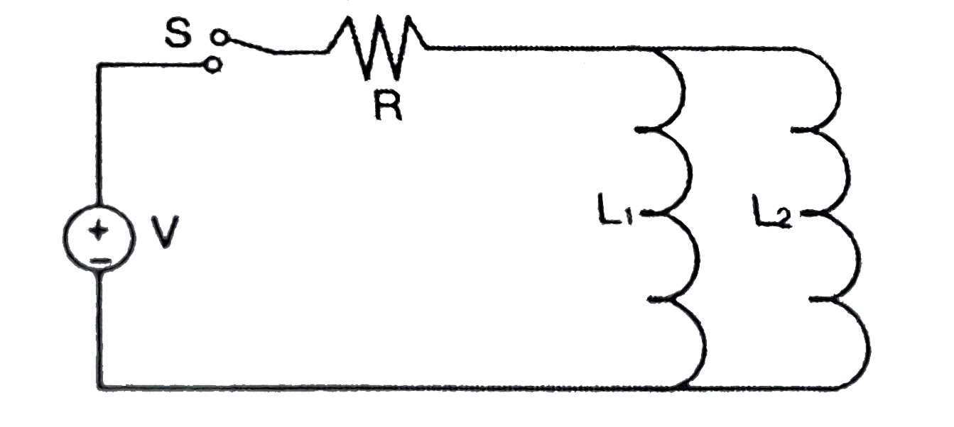
In the circuit, a battery of emf E, a resistance R and inductance coil L1andL2 and switch S are connected as shown. In Fig. Initially the switch is open
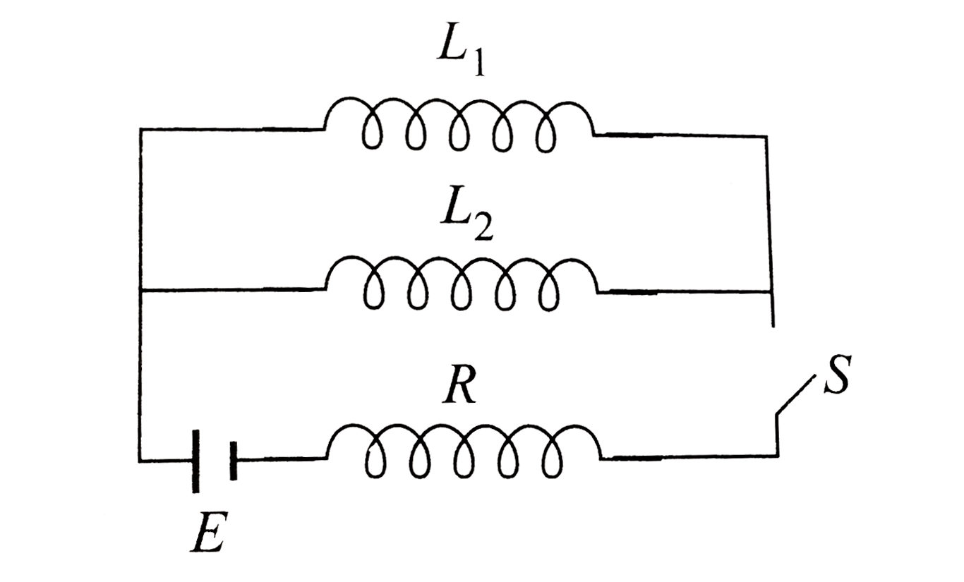
The time constant of the circuit is 1RL1L2L1+L2
Steady state current in the inductor L1is(EL_(2))/(R(L_(1)+L_(2)))
Steady state current in the inductor L2 is EL1R(L1+L2)
In steady the total energy stored in the inductor coils is 12L1L2L1+L2E2R2
The correct Answer is:A, B, C, D
At any time: L1di1dt=L2di2dt
⇒∫i10L1di1=∫i20L2di2⇒L1i1=L2i2⇒i1i2=L2L1 .. (i)
Total steady state current
i=E/R=i1+i2 ..(ii)
From equation (i) and (ii)
i1=EL2R(L1+L2),i2=EL1R(L1+L2)
U=12Leqi2=12(L1L2L1+L2)E2R2.
Topper's Solved these Questions
- MISCELLANEOUS VOLUME 5Book:CENGAGE PHYSICSChapter:MISCELLANEOUS VOLUME 5Exercise:Linked Comprehension
Explore 84 Videos
- MISCELLANEOUS VOLUME 5Book:CENGAGE PHYSICSChapter:MISCELLANEOUS VOLUME 5Exercise:Integer
Explore 12 Videos
- MISCELLANEOUS VOLUME 5Book:CENGAGE PHYSICSChapter:MISCELLANEOUS VOLUME 5Exercise:Integer
Explore 12 Videos
- MISCELLANEOUS VOLUME 3Book:CENGAGE PHYSICSChapter:MISCELLANEOUS VOLUME 3Exercise:True and False
Explore 3 Videos
- Moving charges and magnetismBook:CENGAGE PHYSICSChapter:Moving charges and magnetismExercise:Question Bank
Explore 20 Videos
Similar Questions
In the circuit shown in Fig. emfE , a resistance R, and coil inductances L1 and L2 are known. The internal resistance of the source and the coil resistances are neglible. Find the steady-state currents in the coils after the swich Sw was shorted.

View SolutionTwo capacitors C1andC2 are connected with two batteries of emf ε1 and ε2. The circuit components are connected with a switch S as shown in. Initially the switch is open and the capacitors are charged. Find the heat produced when switch S is closed.
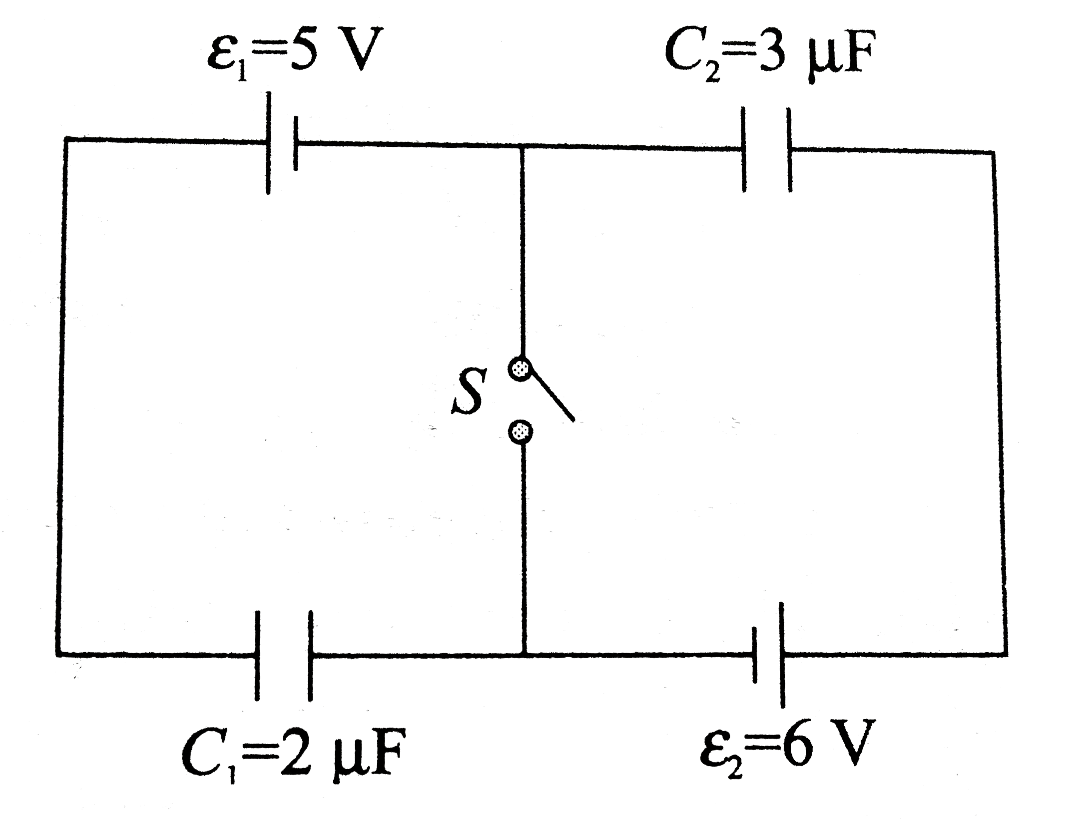 .
.
View Solution
Knowledge Check
The circuit shown consists of a switch (S), a battery (B) of emf E, a resistance R, and an inductor L.
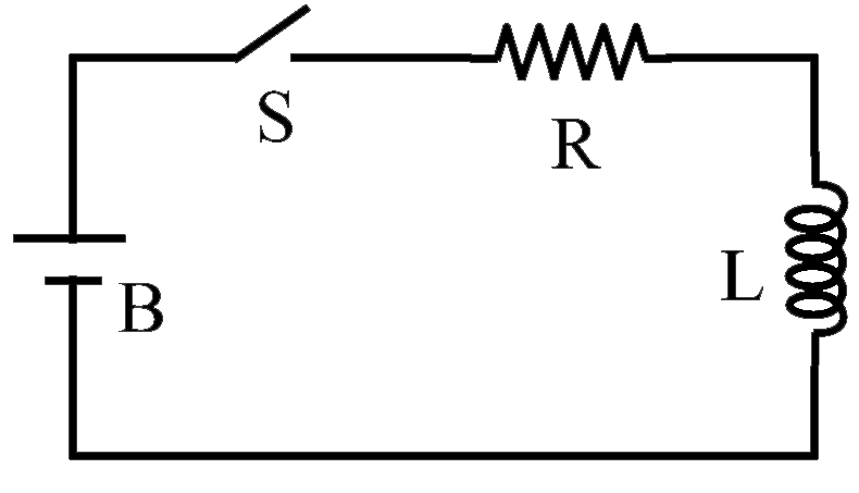
The current in the circuit at the instant the switch is closed is-AE/RBE/R(1−e)C∞D0In the circuit shown, battery, ammeter , and voltmeter are ideal and the switch S is initially closed as shown. When switch S is opened
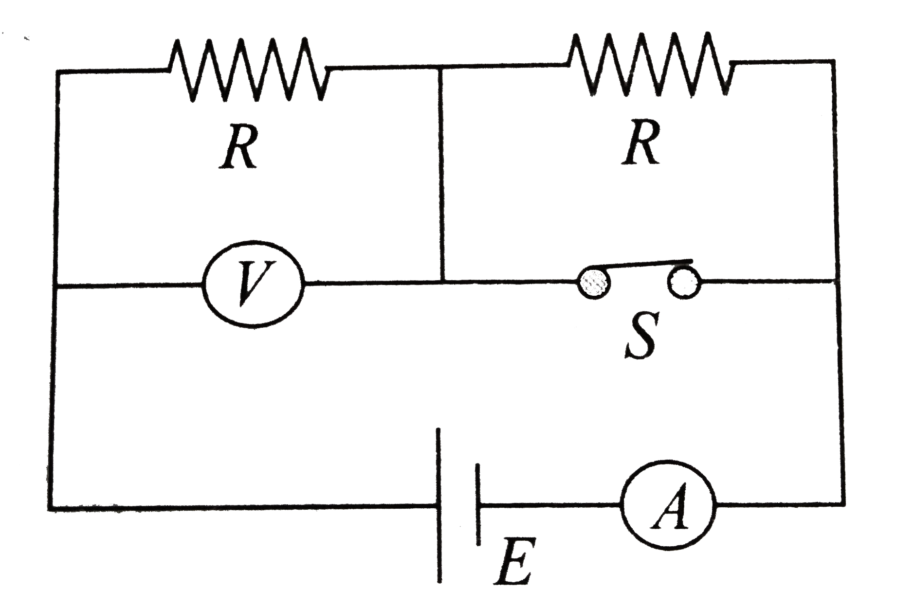 Aequivalent resistance across the battery increasesBpower dissipated by left resistance R increasesCvoltmeter reading decreasesDammeter reading decreases.
A battery of emf 2 V and initial resistance 1Ω is
connected across terminals A and B of the circuit shown
in figure
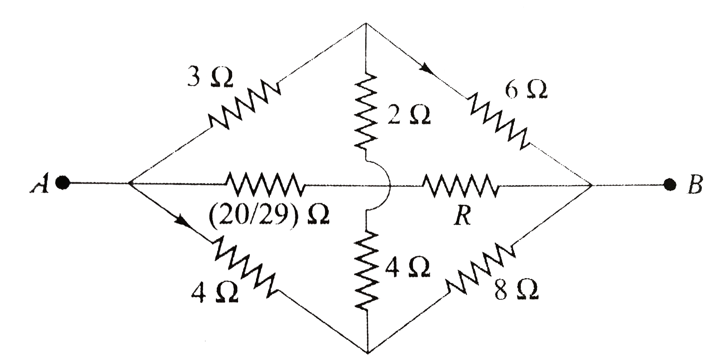 . AThermal power generated in the external circuit will be maximum possible when R=16/25Ω.BMaximum possible thermal power generated in the external circuit is equal to 4 W.CRatio of current through 3Ω to that through 8Ω is independent of R.DNone of above.
A 10(~V) battery, conmected to 5ohm resistance coil having inductance 10 H throughaswitch,drivesaconstantcarrent∈the∘uit,Theswitchissaddenlyope≠dandthetimetaken→openitis2 ms .Iftheavera≥emf∈ducedacrossthecoilisvarepsilon,thenf∈d(E)/(1000).
View SolutionA source of constant voltage V is connected to a resistance R and two ideal inductor L1andL2 through a switch S as shown. There is no mutual inducance between the two inductors. The swtich S is initially open. At t=0, the switch is closed and current begins to flow. Which of the following options is / are correct ?
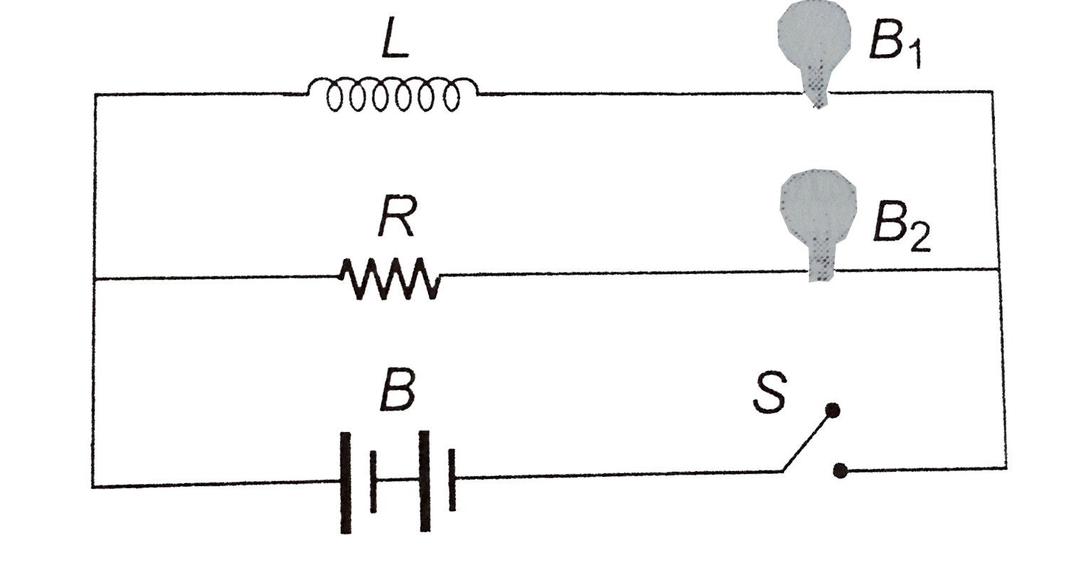
View SolutionAn inductor L , a resistanece R and two identical bulbs, B1 and B2 are connected to a battery through a switch S as shown in the figure. The resistance R is the samem as that of the coil that makes L .Which of the following statement gives the correct description of the happenings when the switch S is closed
View SolutionA 10 V battery connected to 5ω resistance coil having inductance 10 H through a switch drives a constant current in the circuit. The switch is suddenly opened and the time taken to open it is 2ms. The average emf induced across the coil is
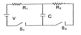
View SolutionA battery of emf V volts, resistances R1 and R2, a condenser C and switches S1, and S2, are connected in a circuit as shown. The capacitor C gets fully charged to V volts when
View Solution

