The circuit shown in the figure is used to transfer energy from one capacitor to another. Initially capacitor of capacitance C1=C0 is charged to a potential difference of V0. Switch S1 is closed at time t = 0. After some time S1 is opened and S2 is closed simultaneously. At time t=T,S2 was opened and it was found that the potential difference across capacitor of capacitance C2=C09 was 3V0. Find the smallest possible value of time T. The coil has inductance L. Assume no resistance.
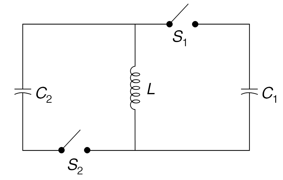
The correct Answer is:Tmin=2π3√LC0
Step by step video, text & image solution for The circuit shown in the figure is used to transfer energy from one capacitor to another. Initially capacitor of capacitance C_(1) = C_(0) is charged to a potential difference of V_(0). Switch S_(1) is closed at time t = 0. After some time S_(1) is opened and S_(2) is closed simultaneously. At time t = T, S_(2) was opened and it was found that the potential difference across capacitor of capacitance C_(2) = (C_(0))/(9) was 3V_(0). Find the smallest possible value of time T. The coil has inductance L. Assume no resistance. by Physics experts to help you in doubts & scoring excellent marks in Class 12 exams.
Updated on:21/07/2023Topper's Solved these Questions
- ELECTROMAGNETIC INDUCTIONBook:ARIHANTChapter:ELECTROMAGNETIC INDUCTIONExercise:Level 3
Explore 12 Videos
- ELECTROMAGNETIC INDUCTIONBook:ARIHANTChapter:ELECTROMAGNETIC INDUCTIONExercise:Level 3
Explore 12 Videos
- CURRENT ELECTRICITYBook:ARIHANTChapter:CURRENT ELECTRICITYExercise:Current Electricity
Explore 105 Videos
- ELECTROSTATICSBook:ARIHANTChapter:ELECTROSTATICSExercise:Level 3
Explore 59 Videos
Similar Questions
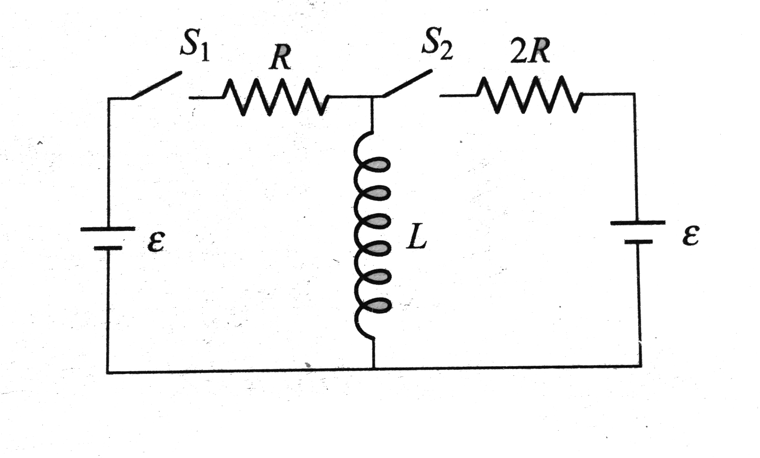
In the circuits shows in S1 and S2 are switches. S2 remains closed for a long time and S1 is opened. Now S1 is also closed. Just after S1 is closed, find the potential difference (V) across R and di/dt (with sign) in L.
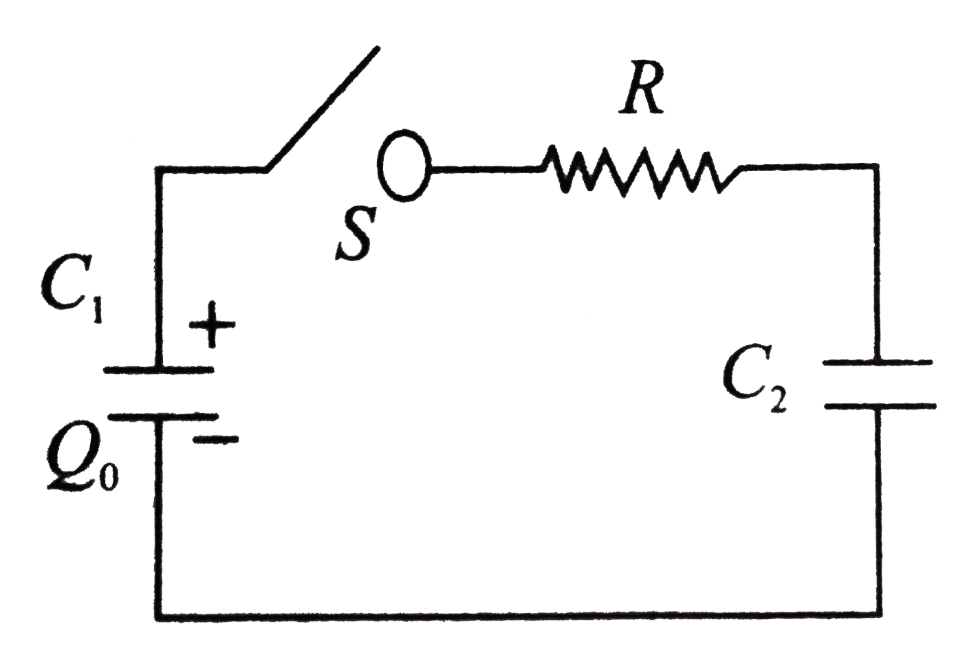
View SolutionIn the circuit shown, the capacitor C1 is initially charged with charge q0. The switch S is closed at time t = 0 . The charge on C2 after time t is
View Solution
Knowledge Check
In the circuit shown in figure-3.345 the capacitor of capacitance C is charged to a potential difference V. The current in the circuit just after the closing of switch S is :
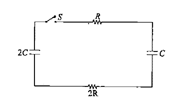 AV3RB3VRCV2RDzero
The switch S in the circuit diagram is closed at t = 0. The charge on capacitors at any time is
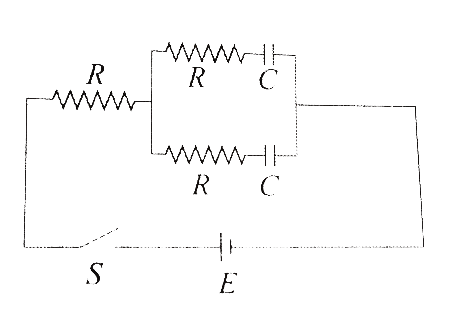 Aqt=EC(1−e−2t/3RC)Bqt=EC(1−e−t/2RC)Cqt=EC(1−e−t/3RC)Dqt=EC(1−e−3t/2RC)
In the circuit shown in fig. C1=2C2 Initially, capacitor C1 is charged to a potential of V. The current in the circuit just after the switch S is closed is
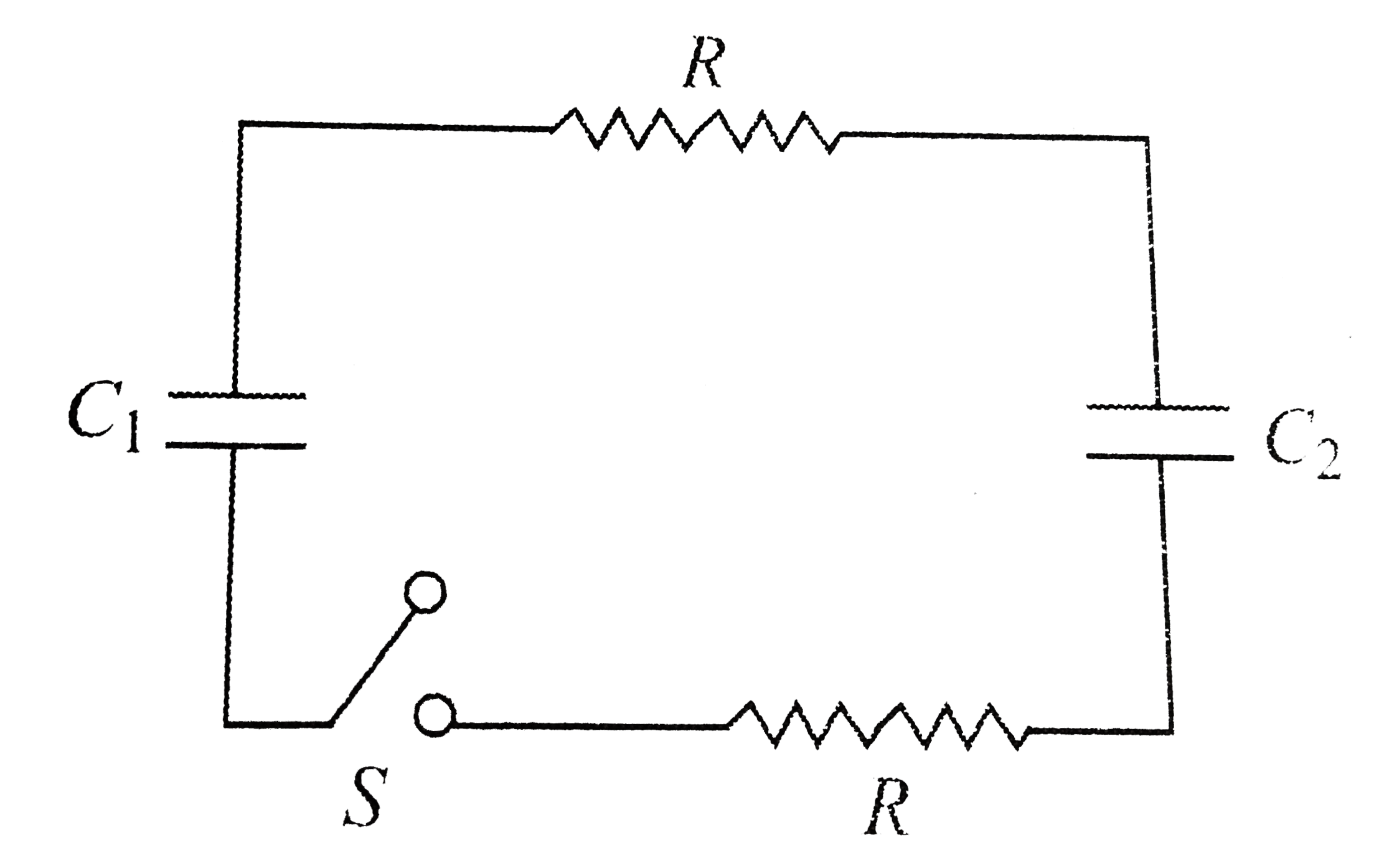 A0B2V/RC∞DV/2R
A capacitor of capacitance C1 is charged to a potential difference V and then connected with an uncharged capacitor of capacitance C2 a resistance R. The switch is closed at t = 0. Choose the correct option(s):
View SolutionTwo capacitors of capacitance C and 3C are charged to potential difference V0 and 2V0 respectively, and connected to an inductor of inductance L as shown in figure. Initially the current in the inductor is zero. Now, the switch S is closed.
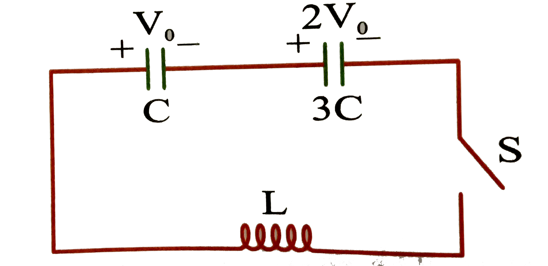
Potential difference across capacitor of capacitance C when the current in the cirucit is maximum is
View SolutionTwo capacitors of capacitance C and 3C are charged to potential difference V0 and 2V0 respectively, and connected to an inductor of inductance L as shown in figure. Initially the current in the inductor is zero. Now, the switch S is closed.
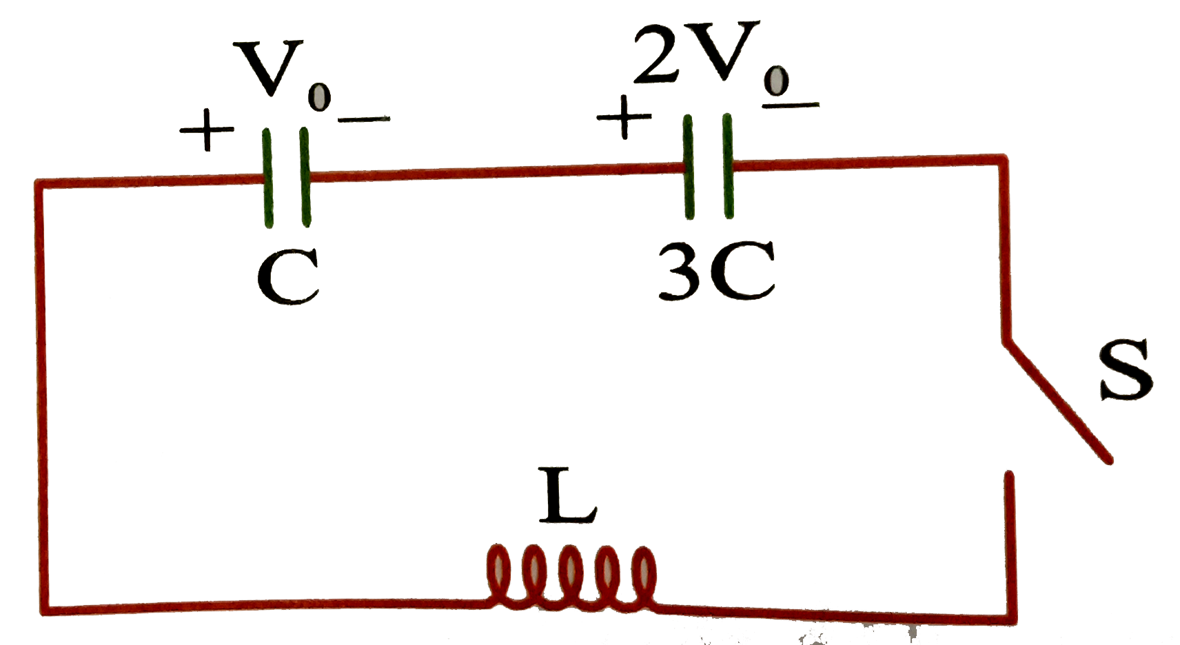
Potential difference across capacitor of capacitance 3C when the current in the cirucit is maximum is :
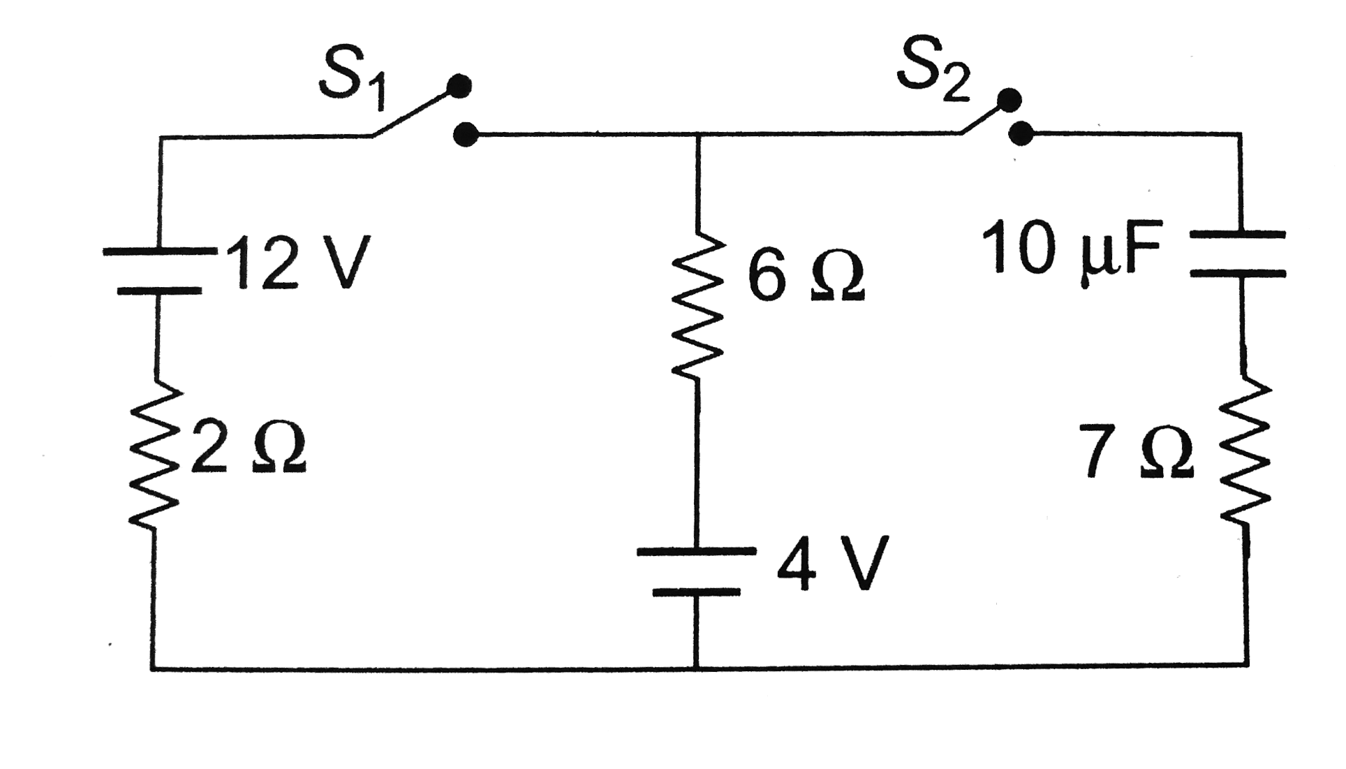
View SolutionIn the circuit shown in the figure, if switches S1 and S2 have been closed for a long time, then charge on the capacitor.
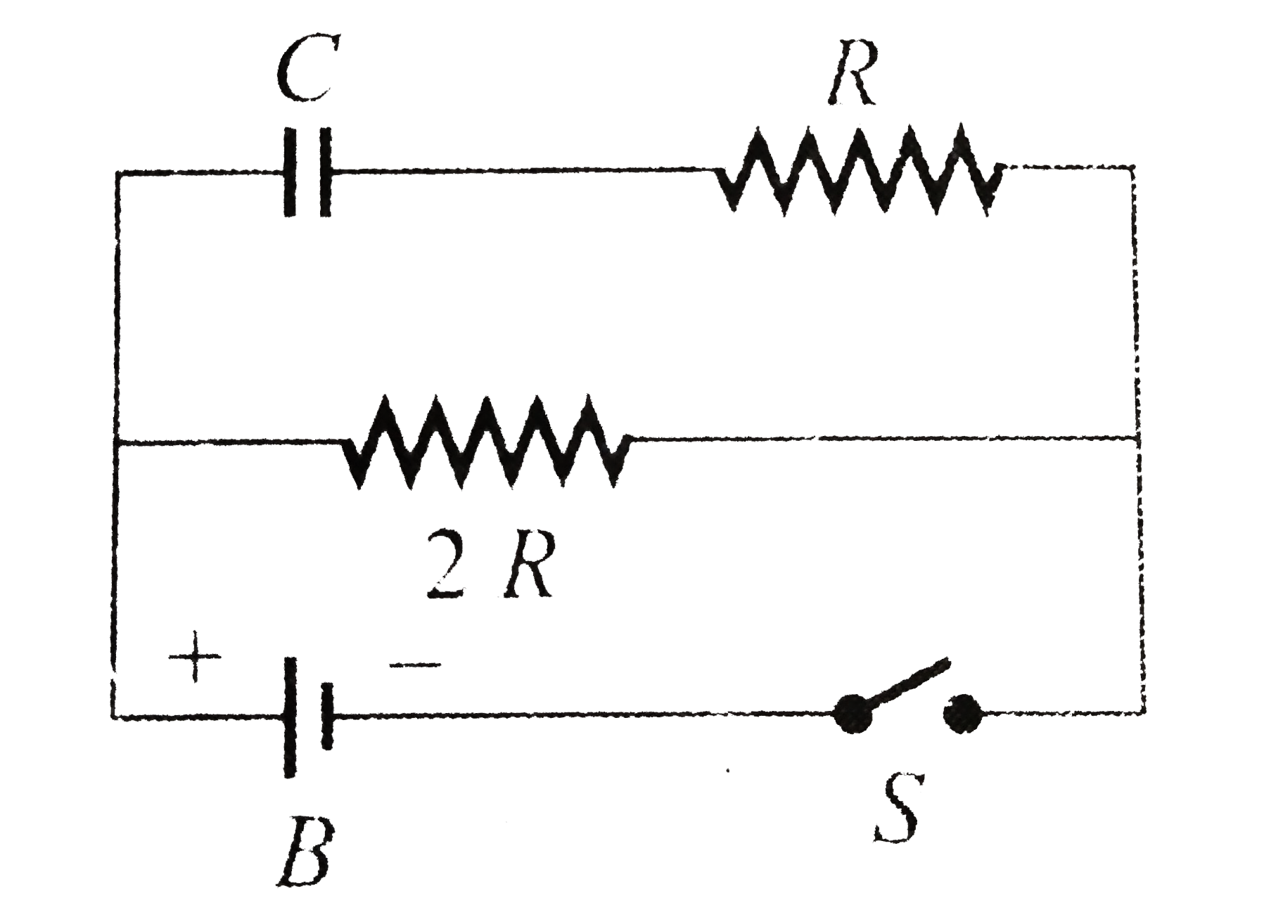
View SolutionIn the circuit shown in fig, if the switch S is closed at t=0 , the capacitor charges with a time constant
View Solution