An alternating voltage V=100sinωt is applied across an LCR circuit as shown. At the instant when voltage drop across source is 50√3 volts then at that instant
R=30Ω XL=60Ω XC=20Ω
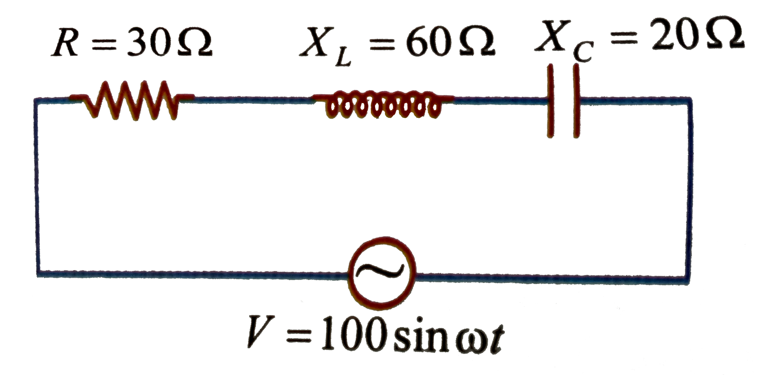
voltage drop across inductor is (120cos7∘) volts
voltage drop across capacitor is (40cos173∘) volts
voltage drop across resistor is (60cos7∘) volts
All the above
The correct Answer is:D
i0=V0√R2+(XL−XC)2=10050=2A
Peak value of voltages
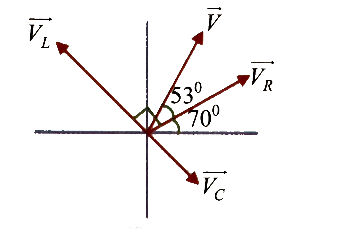
∣∣∣−→VR∣∣∣−i0R=60V
∣∣∣−→VL∣∣∣=i0XL=120V
∣∣∣−→VC∣∣∣=i0XC=40V
Phasor diagram at the instant given
Instantaneous values are components on + y-axix.
Topper's Solved these Questions
- ALTERNATING CURRENTBook:NARAYNAChapter:ALTERNATING CURRENTExercise:LEVEL - VI
Explore 120 Videos
- ALTERNATING CURRENTBook:NARAYNAChapter:ALTERNATING CURRENTExercise:LEVEL - I (H.W)
Explore 23 Videos
- ALTERNATING CURRENTBook:NARAYNAChapter:ALTERNATING CURRENTExercise:LEVEL - IV NCERT Based Questions
Explore 15 Videos
- ATOMIC PHYSICSBook:NARAYNAChapter:ATOMIC PHYSICSExercise:LEVEL-II (H.W)
Explore 14 Videos
Similar Questions
Knowledge Check
An alternating potential E=E0sinωt is applied to a series L-C circuit. What is the phase difference between the voltage across L and C?
Aπ2BπC3π2DzeroAn alternating voltage E=E0sinωt , is applied across a coil of inductor L. The current flowing through the circuit at any instant is
AE0ωLsin(ωt+π/2)BE0ωLsin(ωt−π/2)CE0ωLsin(ωt−π/2)DE0ωLsin(ωt+π/2)An alternative voltage V=10sinωt (in volts) is applied across a parallel arrangement as shown current (in A) through the source is best described by
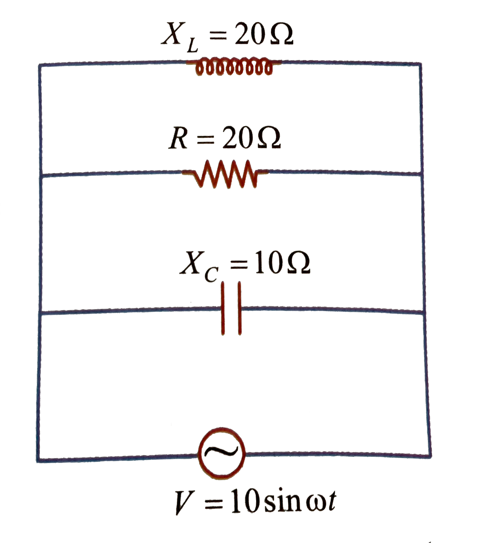 Ai=0.05sinωtBi=0.7sin(ωt+π6)Ci=0.7sin(ωt+π4)Di=0.05sin(ωt+π2)
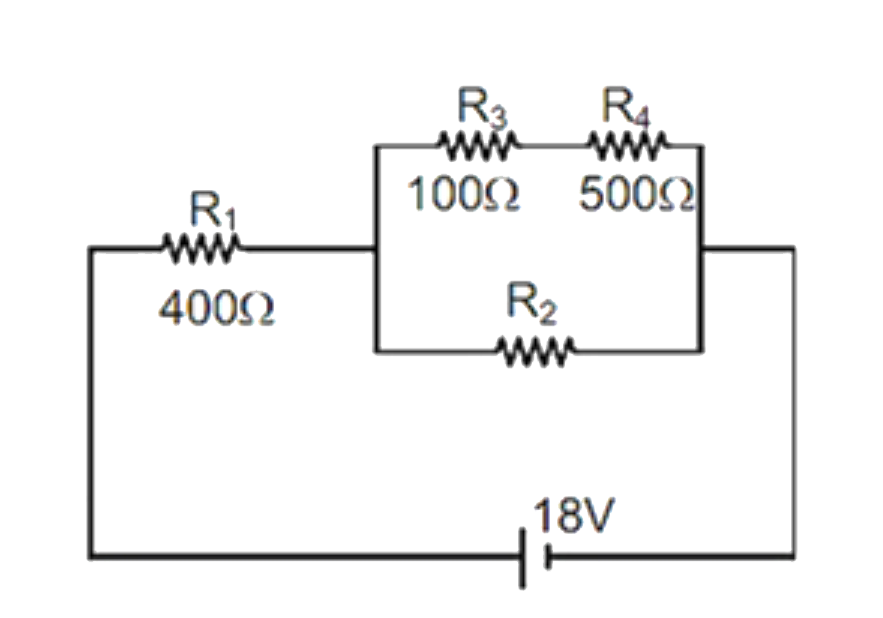
Determine the voltage drop across the resistor R1 in the circuit given below with E = 65V, R_1 = 50 OmegaR_2 = 100 Omega, R_3 = 100 Omega, and R_4 300 Omega.
View SolutionIf the voltage across 500Ω is 5 V. then R2 is
View SolutionAn alternating e.m.f. of 0.1 V is applied across an LCR series circuit having R=2Ω,C=40μFandL=100mH. At resonance, the voltage drop across the inductor is
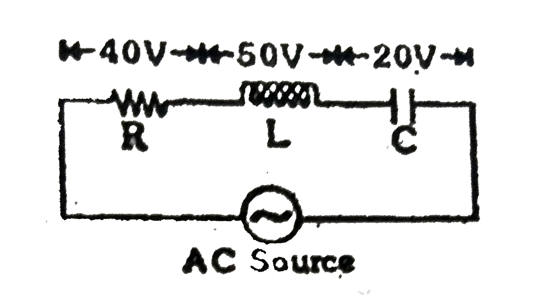
View SolutionIn series LCR circuit, the voltages across R, L and C are shown in the figure. The voltage of applied source
View SolutionAn rms voltage of 110 V is applied across a series circuit having a resistnce 11Ω and an impedance 22Ω. The power consumed is
View Solution


