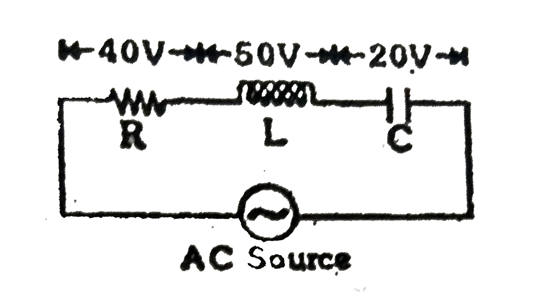
In series LCR circuit, the voltages across R, L and C are shown in the figure. The voltage of applied source

A
110 V
B
10 volt
C
50 volt
D
70 volt
Video Solution
Text Solution
The correct Answer is:C
v=√V2R+(VL−VC)2
v=√402+(50−20)2=50
|
Topper's Solved these Questions
Similar Questions
Knowledge Check
In series LCR circuit, the voltages across R, L and C shown in figure. The voltage of applied source is
 A110 voltB10 voltC50 voltD70 volt
In a series LCR circuit, the voltage across the inductance and capacitance are not
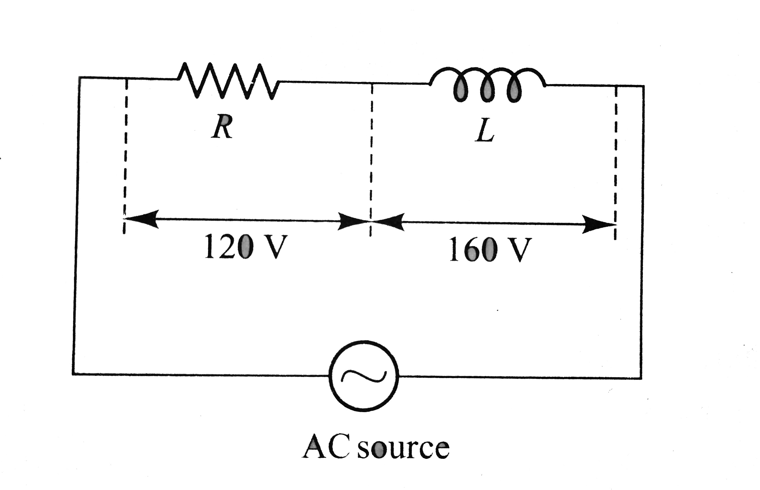
Aout of phase with voltage across resistance by 90∘Bequal in magnitude at resonanceCout of phase with each other by 180∘Din phase with the source voltageThe circuit given in fig. has a resistanceless choke coil L and a resistance R. The voltage across R and L are also given in the figure. The virtual value of the applied voltage is
 A100VB200VC300VD400V
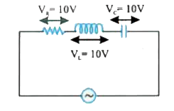
In series L-C-R circuit as shown in figure the voltage of the source is

View SolutionIn a series LCR circuit, voltage drop axross L can be more than applied voltage (True/false).
View SolutionIn an LCR series circuit the voltages across R,L and C at resonance are 40Vand60V respectively the applied voltage is .
View SolutionIn an LCR series ac circuit the voltage across L,C and R are V1,V2 and V3 respectively The voltage of the source is .
View SolutionIn a series LR circuit, the voltage drop across inductor is 8 volt and across resistor is 6 volt. Then voltage applied and power factor of circuit respectively are:
View Solution
