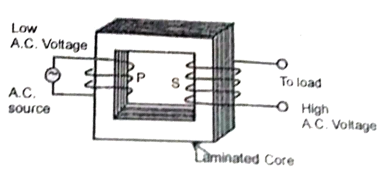
Draw a schematic diagram of a step-up transformer . Explain its working principle . Deduce the expression for the secondary to primary voltage in terms of the number of turns in the two coils . In an ideal transformer , how is this ratio related to the currents in the two coils ?
Step-up transformer : Principle : It is a device which converts low voltage A.C. into high voltage A.C. It is based upon the principle of mutual induction . When alternating current passed through a coil , an induced e.m.f. is set up in the neighbouring coil .
Construction : A transformer consists of two coils of many turns of insulated copper wire wound on a closed laminated iron core . One of the coils known as primary (P) is connected to A.C. supply . The other coil known as secondary (S) is connected to the load.
Working : When an alternating current is passed through the primary , the magnetic flux through the iron core changes which does two things.It produces e.m.f in the primary and an induced. e.m.f is also set up in the secondary . If the primary is negligible , the back e.m.f will be equal to the voltage applied to the primary.
∴ Vp=−NpdϕdtandVs=−Nsdϕdt
where NpandN5 are number turns in the primary and secondary respectively .VpandV5are their respective voltages.
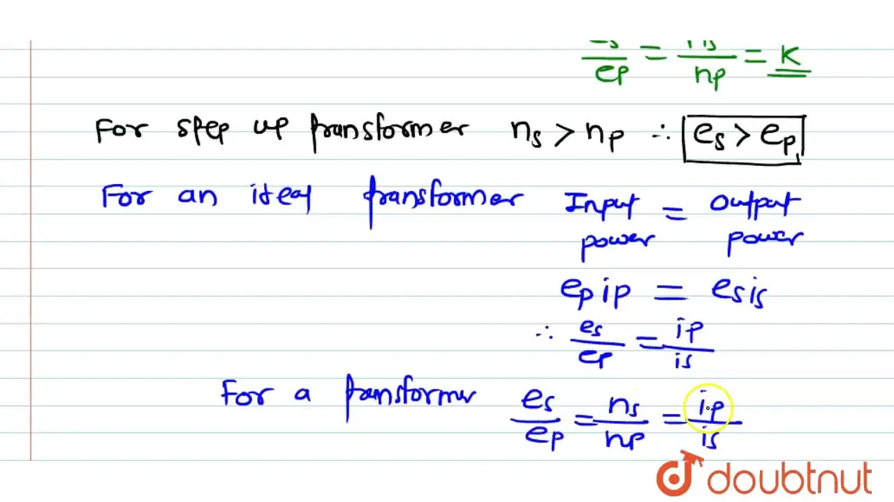
∴ VsVp=NsNp
This ratio NsNp is called the turns ratio
In a step- up transformer : Ns>Np
So, Vs>Vp
Large scale transmission : The large scale transmission and distribution of electrical energy over long distances is done with the use of transformer . The voltage output of the generator is stepped-up-so that current is reduced and power loss I2R is cut down . It is then transmitted over long distances to an area sub- stations and utility poles before a power supply of 240 V reaches our homes .

Related Playlists
- BOOK - XII BOARD PREVIOUS YEAR PAPER ENGLISHCHAPTER - XII BOARDSEXERCISE - SET -II9videos
XII BOARDS
- BOOK - XII BOARD PREVIOUS YEAR PAPER ENGLISHCHAPTER - XII BOARDSEXERCISE - SET -III4videos
XII BOARDS
- BOOK - XII BOARD PREVIOUS YEAR PAPER ENGLISHCHAPTER - XII BOARDSEXERCISE - SET-III DELHI BOARD10videos
XII BOARDS
- BOOK - XII BOARD PREVIOUS YEAR PAPER ENGLISHCHAPTER - SAMPLE PAPER 2019EXERCISE - SECTION D6videos
SAMPLE PAPER 2019
Similar Questions
Draw a circuit diagram of C.E. transistor amplifier. Briefly explain its working and write the expression for (i) current gain (ii) voltage gain of the amplifier.
View Solution(a) Draw a schematic diagram of an AC generator. Explain is working and obtain the expression for the instantaneous value of the emf in terms of the magnetic field B, number of turns N of the coil of area A rotating with angular frequency ω. Show how an alternating emf is generated by loop of wire rotating in a magnetic field.
(b) A circular coil of radius 10 cm and 20 turns is rotated about its vertical diameter with angular speed of 50 rad s−1. in a uniform horizontal magnetic field of 3.0×10⁻²T.
(i) Calculate the maximum and average emf induced in the coil.
(ii) If the coil forms a closed loop of resistance 10Ω, calculate the maximum current in the coil and the average power loss due to Joule heating.View SolutionAssertion : A given transformer can be used to step-up ot step-down the voltage.
Reason : The output voltage depends upon the ratio of the number of turns of the two coils of the transformer.View SolutionDraw a circuit diagram of a full-wave rectifier. Explain its working principle. Draw the input/output wave forms indicating clearly the function of the two diode used.
View SolutionDraw a circuit diagram of a full-wave rectifier. Explain its working principle. Draw the input/output wave forms indicating clearly the function of the two diode used.
View SolutionIn a step-up transformer the turn's ratio is 10. If the frequency of the current in the primary coil is 50Hz then of the frequency of the current in the secondary coil will be
View SolutionDraw a schematic arrangement for winding of primary and secondary coil in a transformer when the two coils are wound on top of each other.
(ii) State the underlying principle of a transformer and obtain the expression for the ratio of secondary to primary voltage in terms of the
(a) number of secondary and primary windings and
(b) primary and secondary currents.
(iii) Write the main assumption involved in deriving the above relations.
(iv) Write any two reasons due to which energy losses may occur in actul transformers.View SolutionA transformer is used to step up an alternating emf of 200V to 440V. If the primary coil has 1000 turns, calculate the number of turns in the secondary coil.
View SolutionThe primary coil of an ideal transformer has 100 turns and the secondary coil has 600 turns. Then
View SolutionA step - up transformer is used on 120 V line to provide a potential difference of 2400 V . If the number of turns in the primary is 75, then the number of turns in the secondary shall be
View Solution


