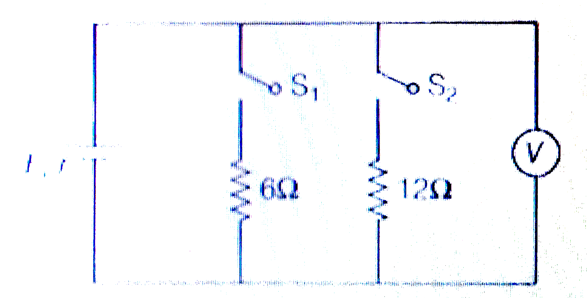
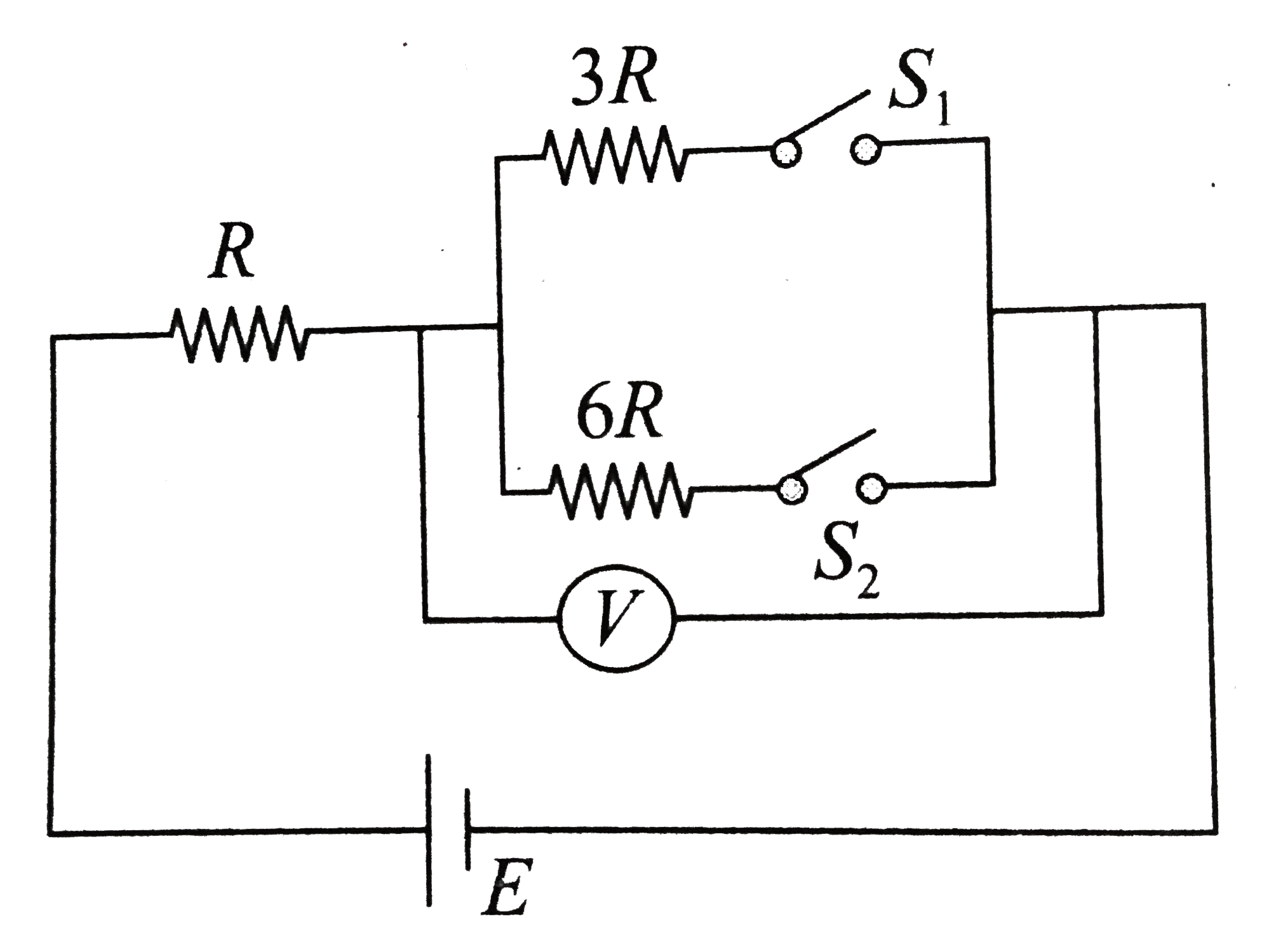
In the circuit shown in figure when switch S1 is closed and S2 is open, the ideal voltmeter shows a reading of 18 V. When switch S2 is closed and S1 is open, the reading of the voltmeter is 24 V. When S1 and S2 both are closed the voltmeter reading will be
14.4V
20.6V
24.2V
10.8V
18=6E6+rand24=12E12+r⇒r=6Ω,E=36V
6∣∣12=4Ω⇒ Reading =36×44+6=14.4V
Topper's Solved these Questions
- DC CIRCUITBOOK - VMC MODULES ENGLISHCHAPTER - DC CIRCUITEXERCISE - LEVEL-1 DAILY TUTORIAL SHEET-4
15 Videos
- DC CIRCUITBOOK - VMC MODULES ENGLISHCHAPTER - DC CIRCUITEXERCISE - LEVEL-1 DAILY TUTORIAL SHEET -5
15 Videos
- DC CIRCUITBOOK - VMC MODULES ENGLISHCHAPTER - DC CIRCUITEXERCISE - LEVEL-1 DAILY TUTORIAL SHEET-2
15 Videos
- CURRENT ELECTRICITYBOOK - VMC MODULES ENGLISHCHAPTER - CURRENT ELECTRICITYEXERCISE - IN-CHAPTER EXERCISE-F
10 Videos
- DYNAMICS OF A PARTICLEBOOK - VMC MODULES ENGLISHCHAPTER - DYNAMICS OF A PARTICLEEXERCISE - JEE Advance (Archive) Level - II (SINGLE OPTION CORRECT TYPE )
31 Videos
Similar Questions
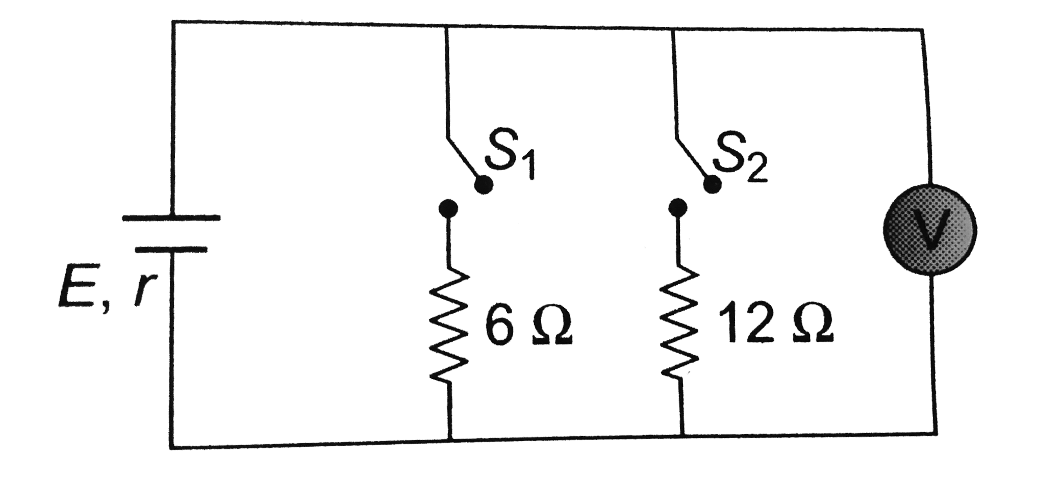
In the circuit shown, when switch S1 is closed and S2 is open, the ideal voltmeter shows a reaiding of 18V. When switch S2 is closed and S1 is open, the reading of voltmeter is 24V. When S1 and S2 both are closed, the voltmeter reading will be
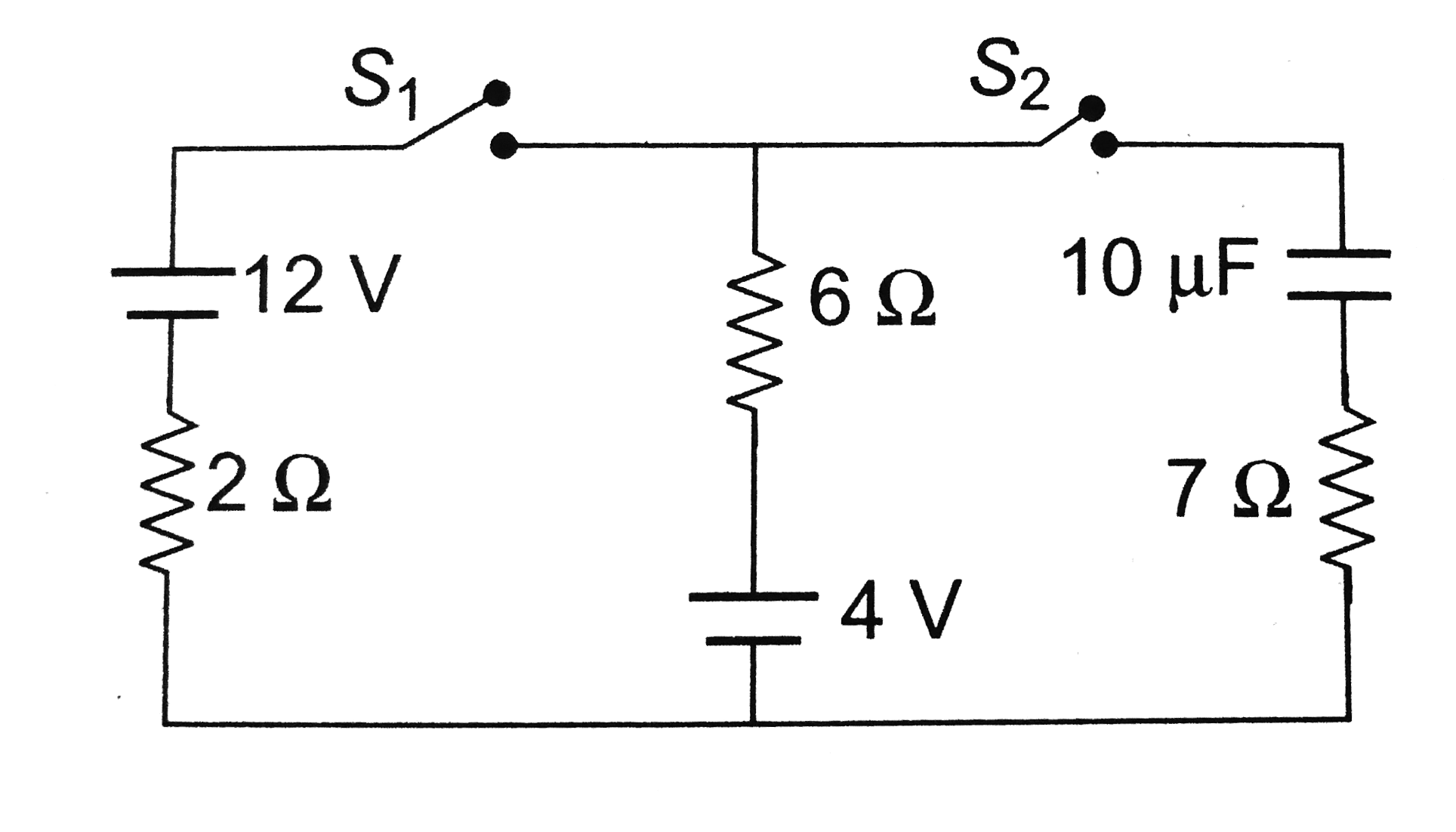
View SolutionIn the circuit shown in the figure, if switches S1 and S2 have been closed for a long time, then charge on the capacitor.
View Solution
Knowledge Check
In the circuit P≠R, the reading of the galvanometer is same with switch S open or closed. Then
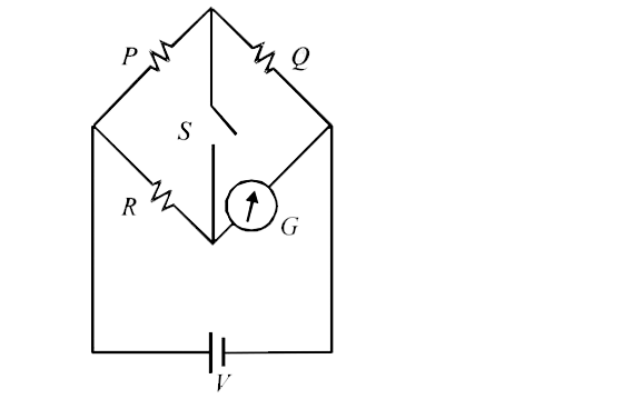 AIR=IGBIP=IGCIQ=IGDIQ=IR
In the circuit shown in figure, reading of voltmeter is V1 when only S1 is closed, reading of voltmeter is V2 when only S2 is closed, and reading of voltmeter is V3 when both S1andS2 are closed. Then .
View SolutionIn the circult shown
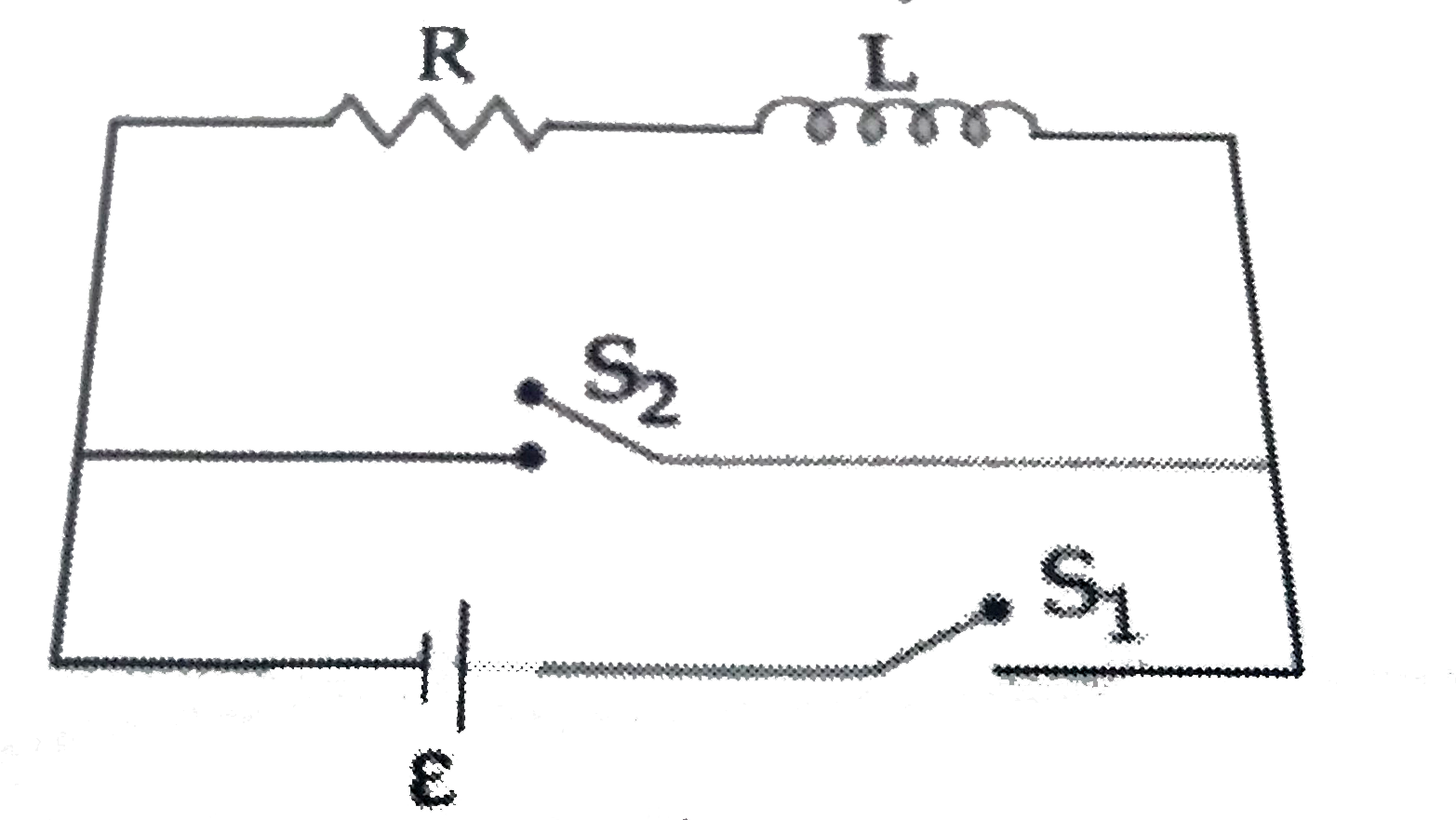 the switch S1 is closed at time t=0 and the swith S2 is kept open. At some later time (t0) ,the swith S1 is opened and S2 is closed .The behaviour of the current I as a function of time 't' is given by :
View SolutionConsider the circuit shown in the figure, the cell is ideal. The readings of the ideal voltmeters V1 and V2 in volts are respectively.

View SolutionFind the charge flown when the switch S is closed.
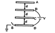
View SolutionConsider the network shown in initially, the switch S1 is closed and S2 is open.
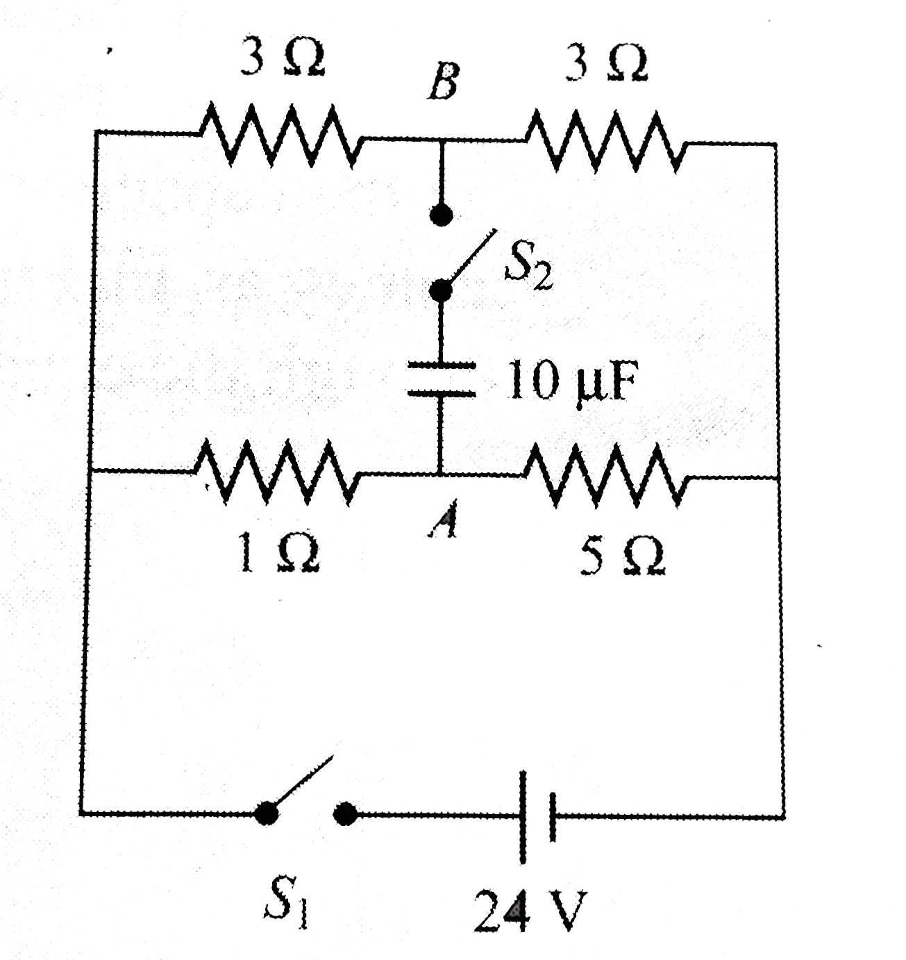
a. Calculate VA−VB.
b. When S2 is also closed, what is VA−VB
i. just after closing , ii. After long time.
View SolutionOn closing the switch S in the circuit as shown in the figure, the reading of the galvanometer G

View SolutionConsider the situation shown in figure. The switch S is open for a long time and then closed.

Find the charge flown through the battery when the switch S is closed.
View Solution
