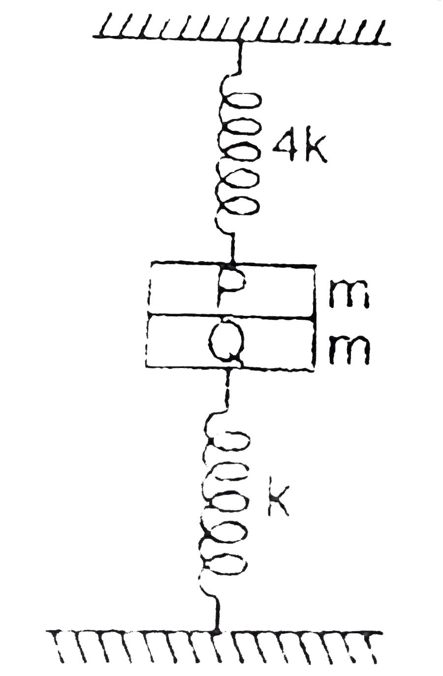
In the figure shown, blocks P and Q are in contact but do not stick to each other. The lower face of P behaves as a plane mirror. The springs are in their natural lengths. The system is released from rest. Then the distance between P and Q when Q is at the lowest point first time will be
2mgK
mgK
4mgK
0
The correct Answer is:A
Both blocks loose contact immediately after the release
TP=2π√m4K.TQ=2π√mK
∴TQ=2TP
Q comes at lowest position at time TQ2 travelling a distance 2mgK downwards.
In time TQ2, i.e. time period of P(TP) the block P come back to original position
∴ Time distance P and Q is 2mgK
Topper's Solved these Questions
- DAILY PRACTICE PROBLEMBOOK - RESONANCE ENGLISHCHAPTER - DAILY PRACTICE PROBLEMEXERCISE - DPP No.32
9 Videos
- DAILY PRACTICE PROBLEMBOOK - RESONANCE ENGLISHCHAPTER - DAILY PRACTICE PROBLEMEXERCISE - DPP No.33
20 Videos
- DAILY PRACTICE PROBLEMBOOK - RESONANCE ENGLISHCHAPTER - DAILY PRACTICE PROBLEMEXERCISE - DPP No.30
9 Videos
- CURRENT ELECTRICITYBOOK - RESONANCE ENGLISHCHAPTER - CURRENT ELECTRICITYEXERCISE - High Level Problems (HIP)
19 Videos
- ELECTRO MAGNETIC WAVESBOOK - RESONANCE ENGLISHCHAPTER - ELECTRO MAGNETIC WAVESEXERCISE - Exercise 3
27 Videos
Similar Questions
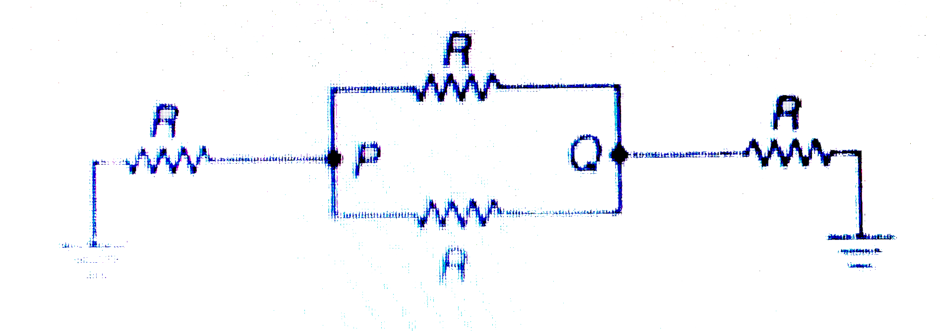
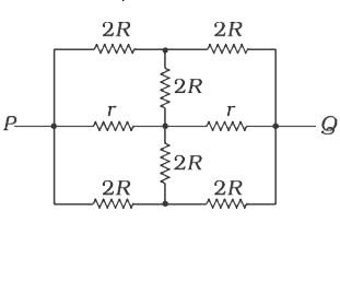
The net resistance between points P and Q in the circuit shown in figure is
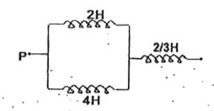
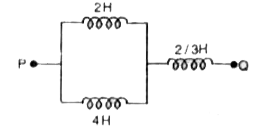
View SolutionThe equivalent inductance between points P and Q in the figure is :
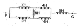
View SolutionThe equivalent inductance between points P and Q in the figure is
View SolutionIn the above question, the velocity of the image of Q in plane mirror of block P with respect to ground when Q is at the lowest point first time is:
View SolutionThe equivalent inductance between points P and Q in figure is :
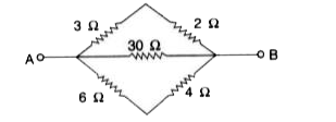
View SolutionCalculate the equivalent resistance between the points A and B in Fig.
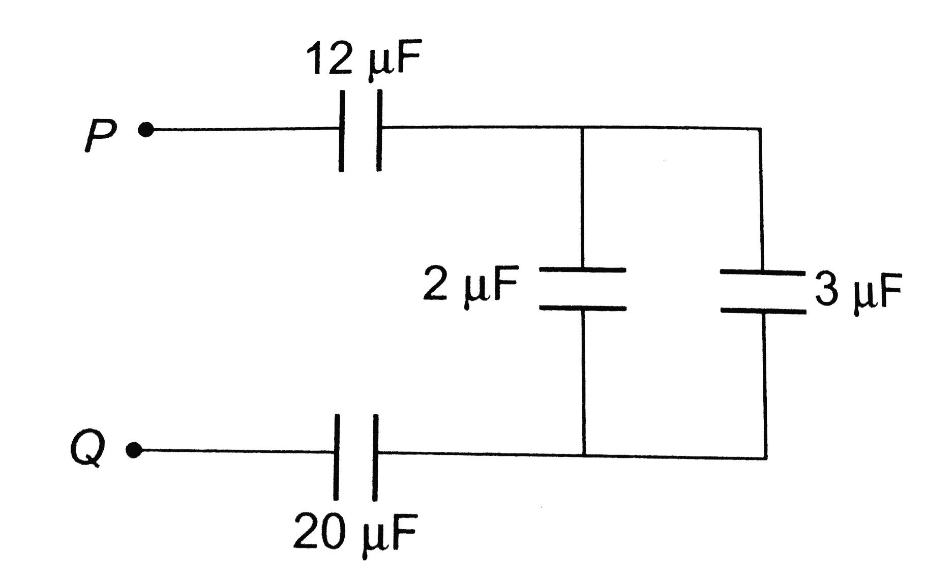
View SolutionIn the circuit diagram shown in the adjoining figure, the resultant capacitance between P and Q is
View SolutionThe effective resistance between points P and Q of the electrical circuit shown in the figure is
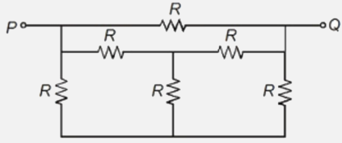
View SolutionThe effective resistance between points P and Q of the electrical circuit shown in the figure is :
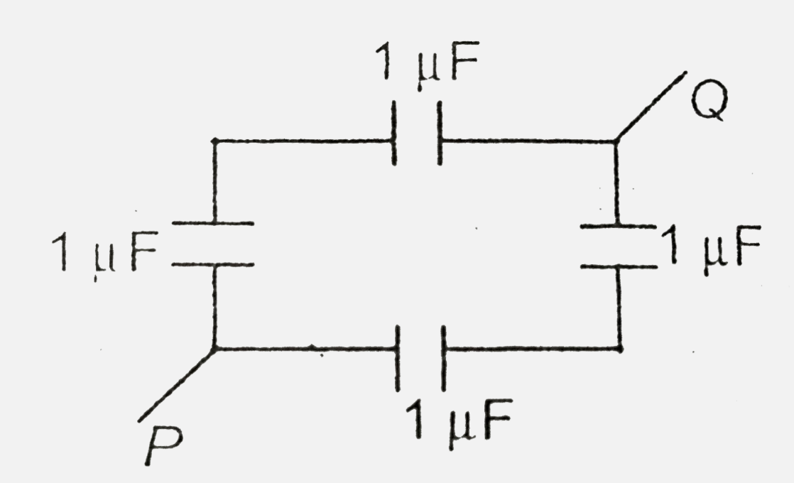
View SolutionFour capacitors are connected as shown in the figure. The equivalent capacitance between P and Q is
View Solution
