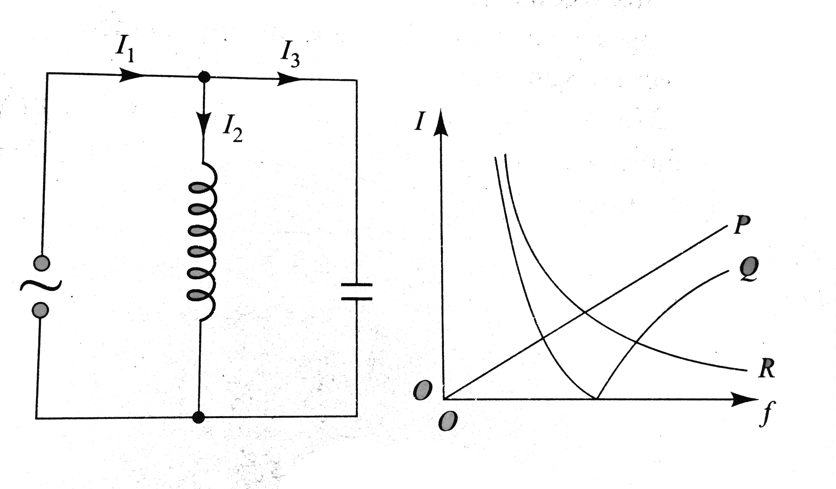
In the circuit shown if fig, the rms currents (I1),(I2) and(I3) are altered by varying the frequency f of the oscillator. The output voltage of the oscillator remains sinusoidal and has a fixed amplitude.
When curves in figure correctly indicate the variation with frequency of the currents (I1),(I2),and(I3).
A
(A)(I1)=Q, (I2)=Q, (I3)=Q
B
(B)(I1)=R, (I2)=Q, (I3)=Q
C
(C) (I1)=Q, (I2)=P, (I3)=R
D
(D)(I1)=Q, (I2)=R, (I3)=P
Video Solution
Text Solution
The correct Answer is:D
Rectancae of the inductor O is given by XL=2πfL.
Therefore, rms current through inductor L is (I2)
=V2πfL∝1f where V is the rms of the supply voltage .
Reactance of the capacitor C is given by (XC)=12πfC
therefore, rms current through the capacitor is
(I3)=VXC=2πfCV∝f
The total current (I1) is given by (I1)=(I2)+(I3)
(V2πfL−2πfCV)
thus, (I2) is best represented by curve R.
(I3) is best represented by curve P.
(I1) is best represented by curve Q.
|
Topper's Solved these Questions
- ALTERNATING CURRENTBOOK - CENGAGE PHYSICS ENGLISHCHAPTER - ALTERNATING CURRENTEXERCISE - Exercises Multiple Correct
5 Videos
- ALTERNATING CURRENTBOOK - CENGAGE PHYSICS ENGLISHCHAPTER - ALTERNATING CURRENTEXERCISE - Exercises Assertion-reasoning
7 Videos
- ALTERNATING CURRENTBOOK - CENGAGE PHYSICS ENGLISHCHAPTER - ALTERNATING CURRENTEXERCISE - Exercises Subjective
15 Videos
- ATOMIC PHYSICSBOOK - CENGAGE PHYSICS ENGLISHCHAPTER - ATOMIC PHYSICSEXERCISE - ddp.4.3
15 Videos
Similar Questions
Knowledge Check
In the circuit shown, the value of currents I1,I2andI3 are
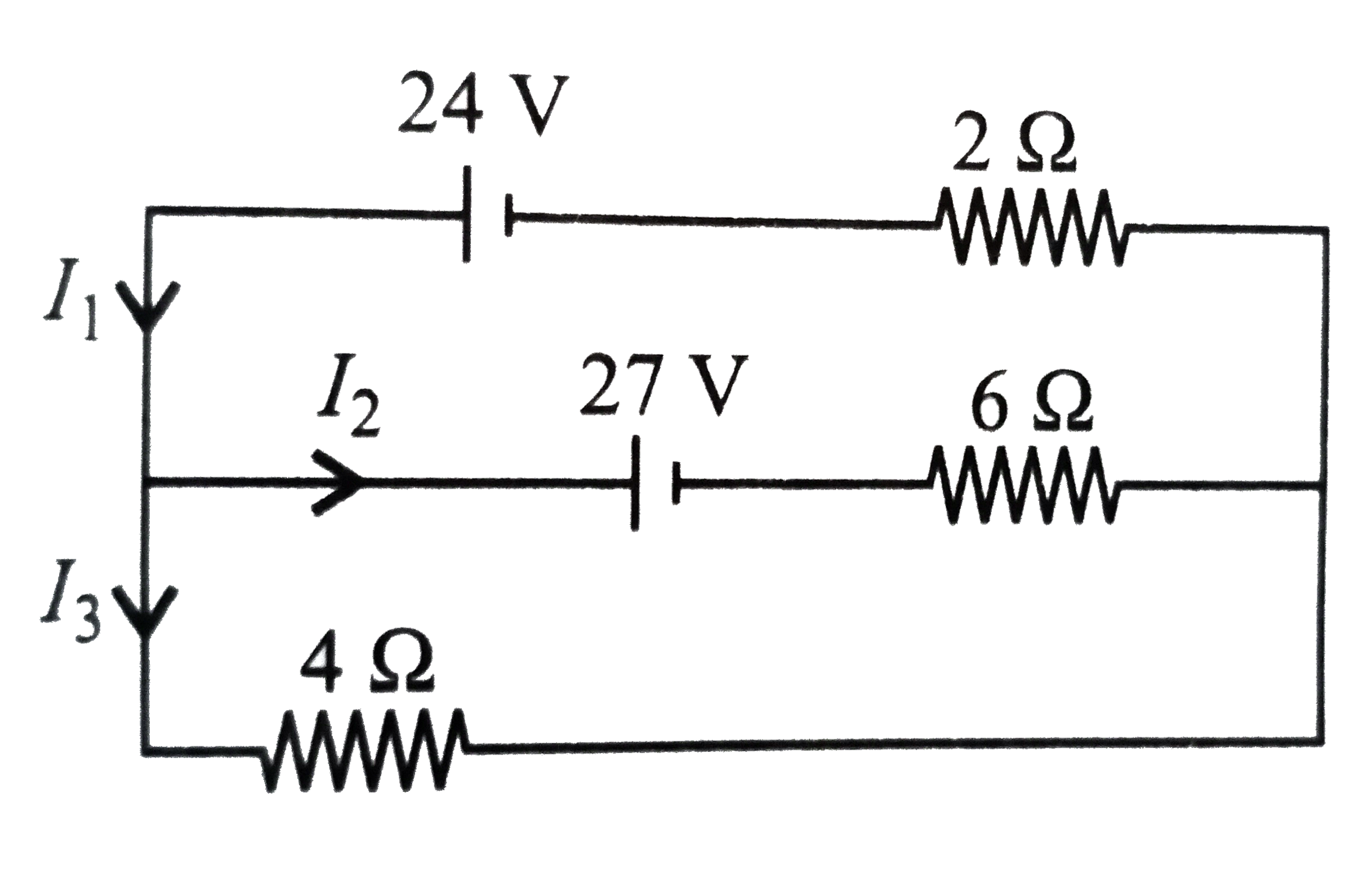 A3A,−3A2A,92AB92A,−32AC5A,4A,−3AD7A,54A,92A
In the circuit shown in fig., the value of I1+I2 is
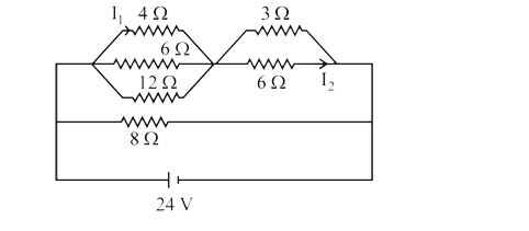
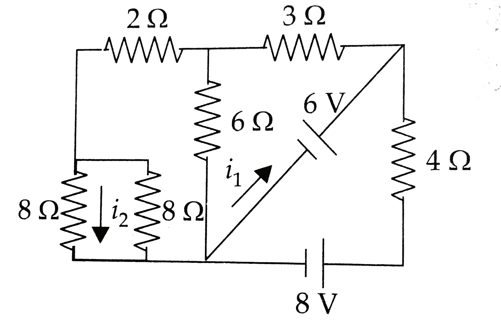
View SolutionIn the circuit as shown in figure, the ratio of current i1/i2 is
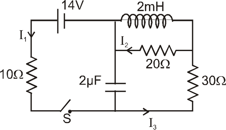
View SolutionIn the circuit shown, the switch is closed at t=0, the currents I1,I2 and I3 are
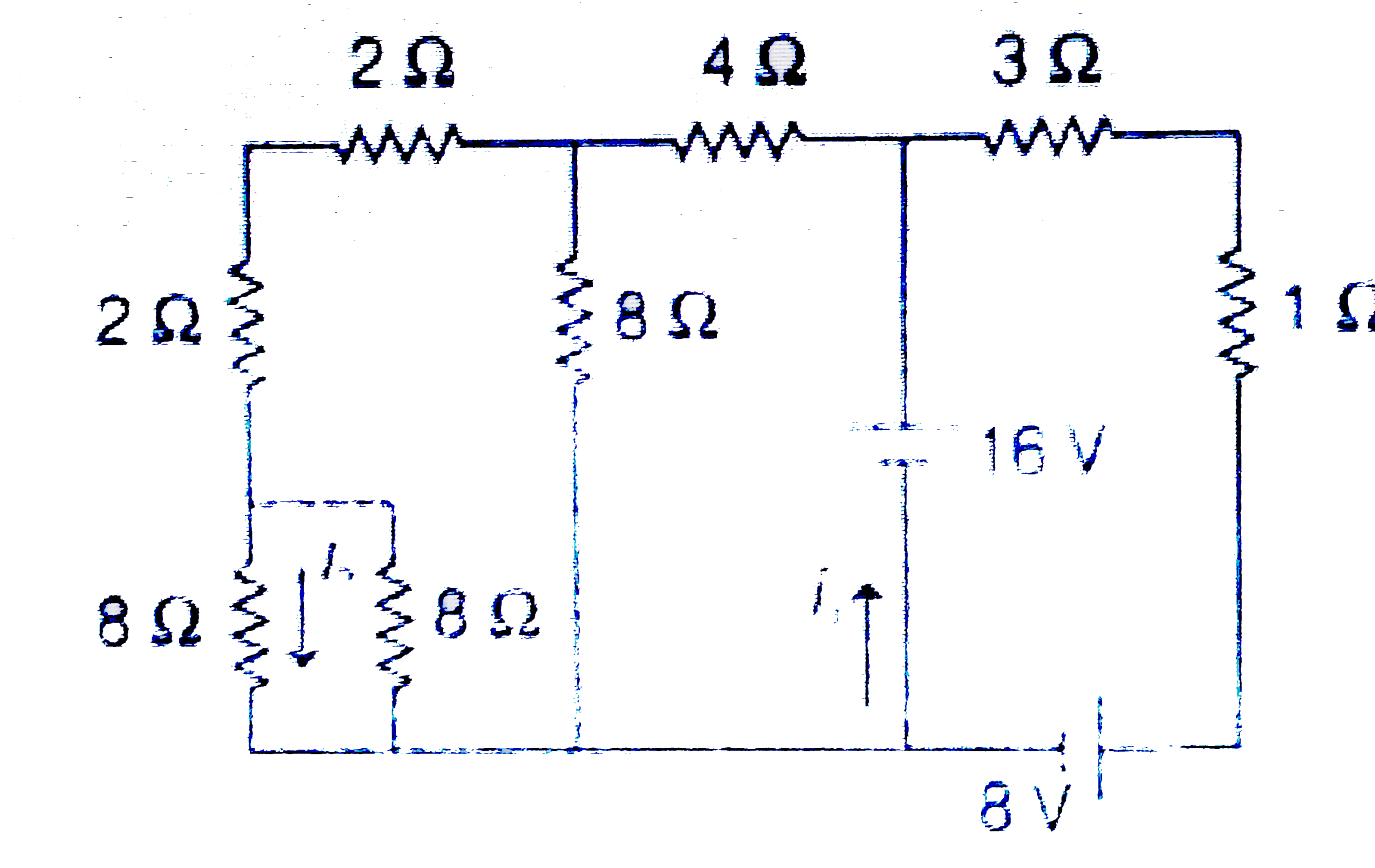
View SolutionIn the circuit shown in figure ,find the ratio of currents i1/i2.
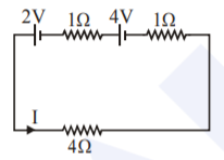
View SolutionFor the circuit shown in the figure current I will be
View SolutionIn the circuit shwon in fig. the current I has a value equal to

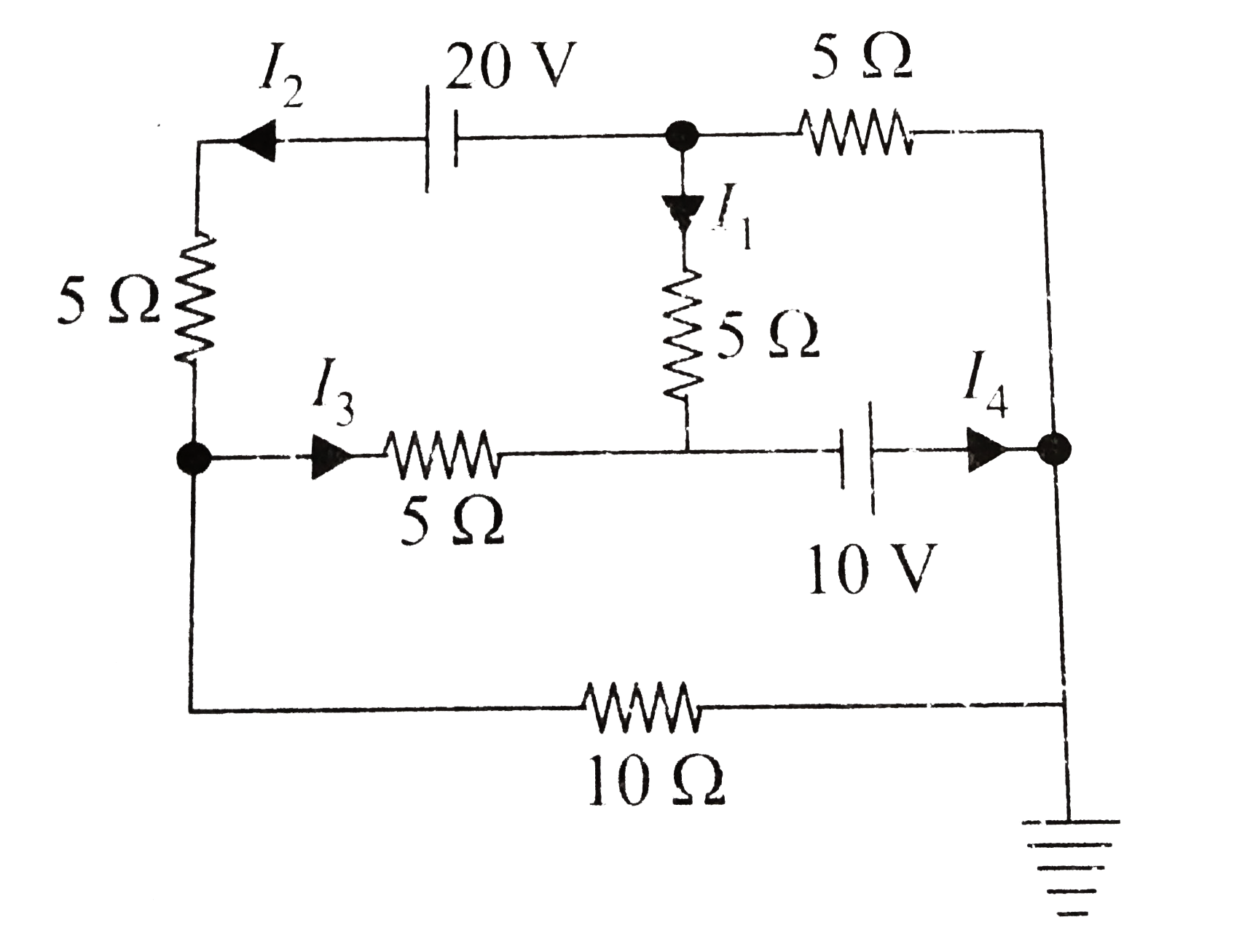
View SolutionIn the circuit shown in the figure
 .
.
The value of current I4 is
View Solution

