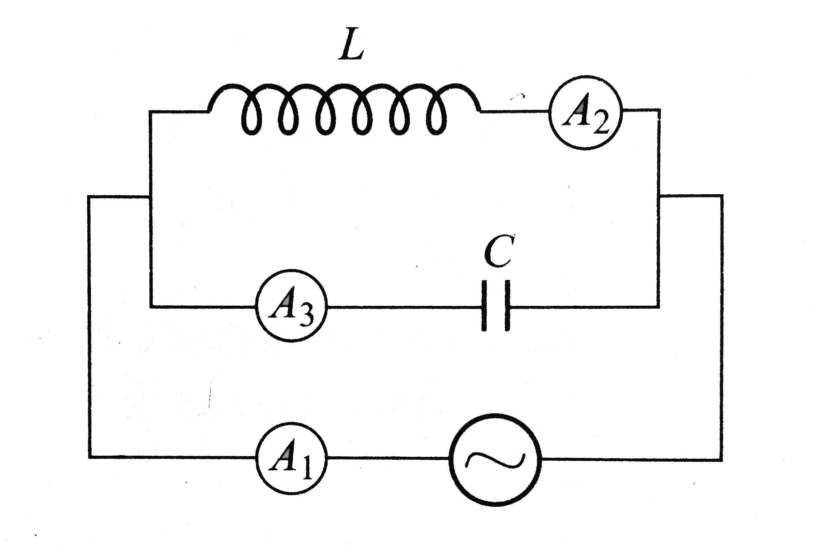
For the circuit shown in fig, the ammeter A2 reads 1.6A and ammeter (A3) reads 0.4A. Then
(A) ω=4√LC
(B)f=2π√LC
(C)The ammeter (A1) reads 1.2 A
(D)the ammeter (A1) reads 2A
The correct Answer is:C
The current of 1.6 A algs emf in phase by (π)/(2). The current of 0.4 A leads emf in phase by π2. So, these two currents are 180∘ out of phase with each other.
∴ Net current (I1)=(1.6−0.4)A=1.2A
1.6=EvXLand0.4=EvXC
⇒XCXL=4⇒1omega C omega L=4
⇒ω=(1).(2√LC)
⇒f=ω2π=14π√LC
Topper's Solved these Questions
- ALTERNATING CURRENTBook:CENGAGE PHYSICS ENGLISHChapter:ALTERNATING CURRENTExercise:Exercises Multiple Correct
Explore 5 Videos
- ALTERNATING CURRENTBook:CENGAGE PHYSICS ENGLISHChapter:ALTERNATING CURRENTExercise:Exercises Assertion-reasoning
Explore 7 Videos
- ALTERNATING CURRENTBook:CENGAGE PHYSICS ENGLISHChapter:ALTERNATING CURRENTExercise:Exercises Subjective
Explore 15 Videos
- ATOMIC PHYSICSBook:CENGAGE PHYSICS ENGLISHChapter:ATOMIC PHYSICSExercise:ddp.4.3
Explore 15 Videos
Similar Questions
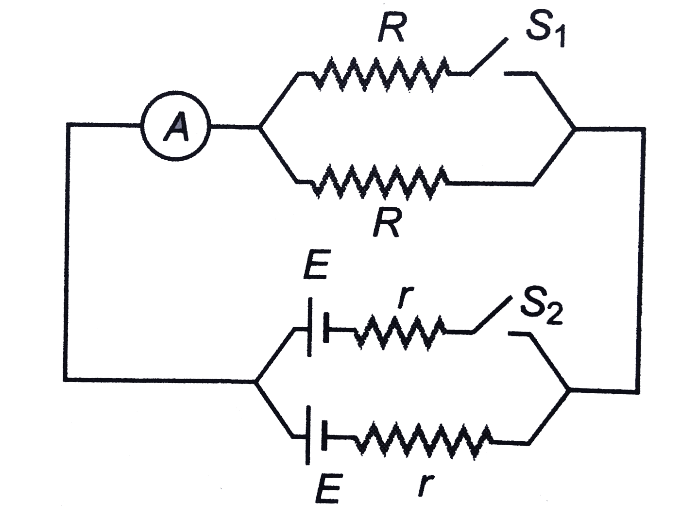
In the circuit shown in figure, reading of ammeter will
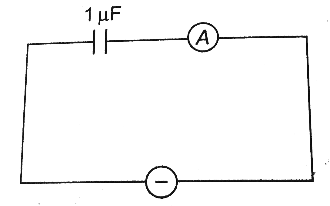
View SolutionIn the circuit shown in figureure, the reading of the AC ammeter is
 .
.
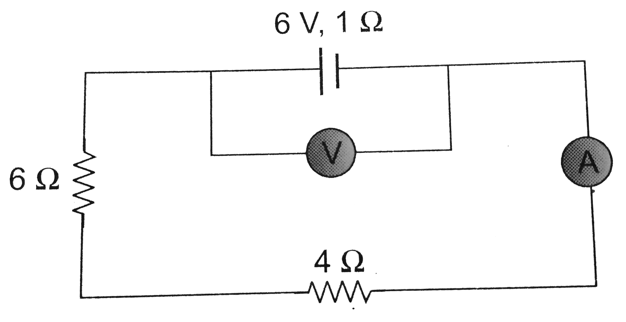
View SolutionIn the circuit shown here, the readings of the ammeter and voltmeter are
View SolutionAn ammeter A, a voltmeter V and a resistance R are connected as shown in the figure. If the voltmeter reading is 1.6V and the ammeter reading is 0.4A, then R is
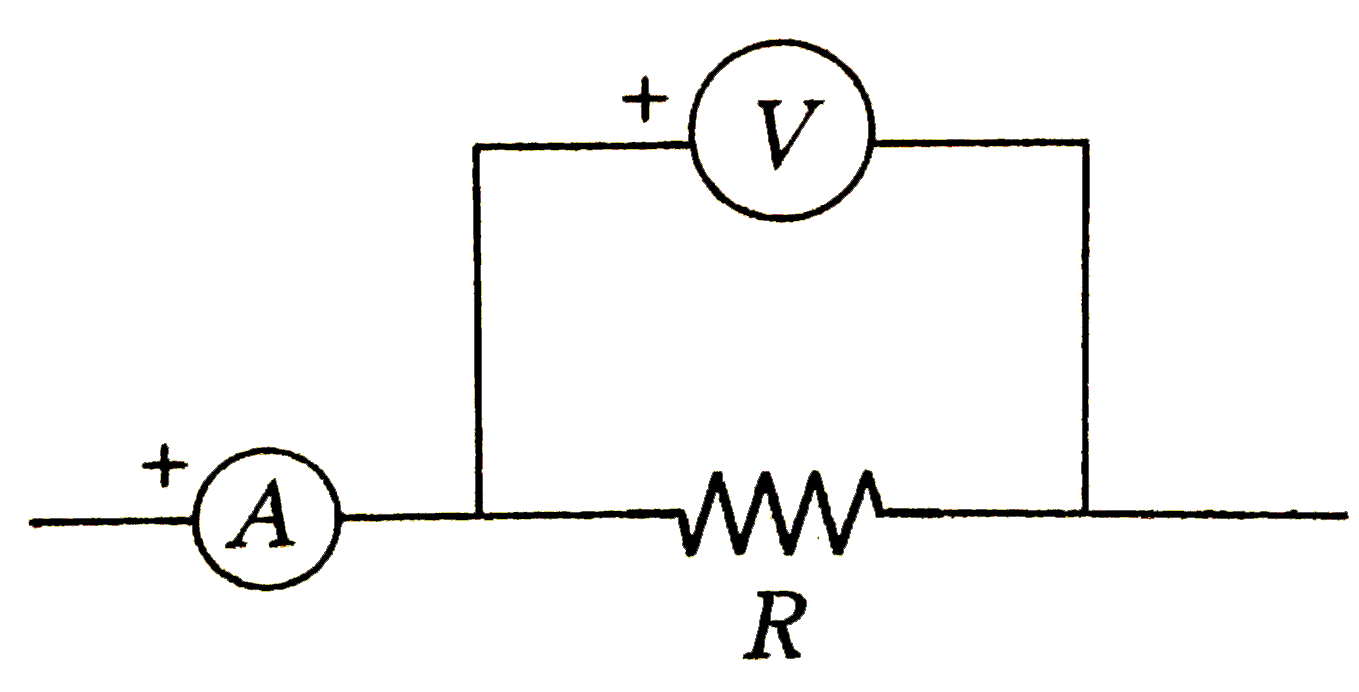
View SolutionA students connects an ammeter Aand a voltmeter V to measure a resistancer as shown in figure. If the voltmeter reads 20V and the ammeter reads 4A, then R is

View SolutionIn the circuit shown in figure, what will be the readings of voltmeter and ammeter?
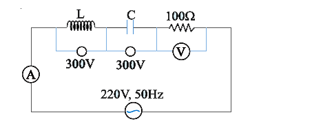
View SolutionA student connects a voltmeters, ammeter and resistance according to the circuit given. If the voltmeter reading is 20V and ammeter reading is 4A, then the resistance will be

View SolutionIn the circuits shown below, the readings of the voltmeters and the ammeters will be:
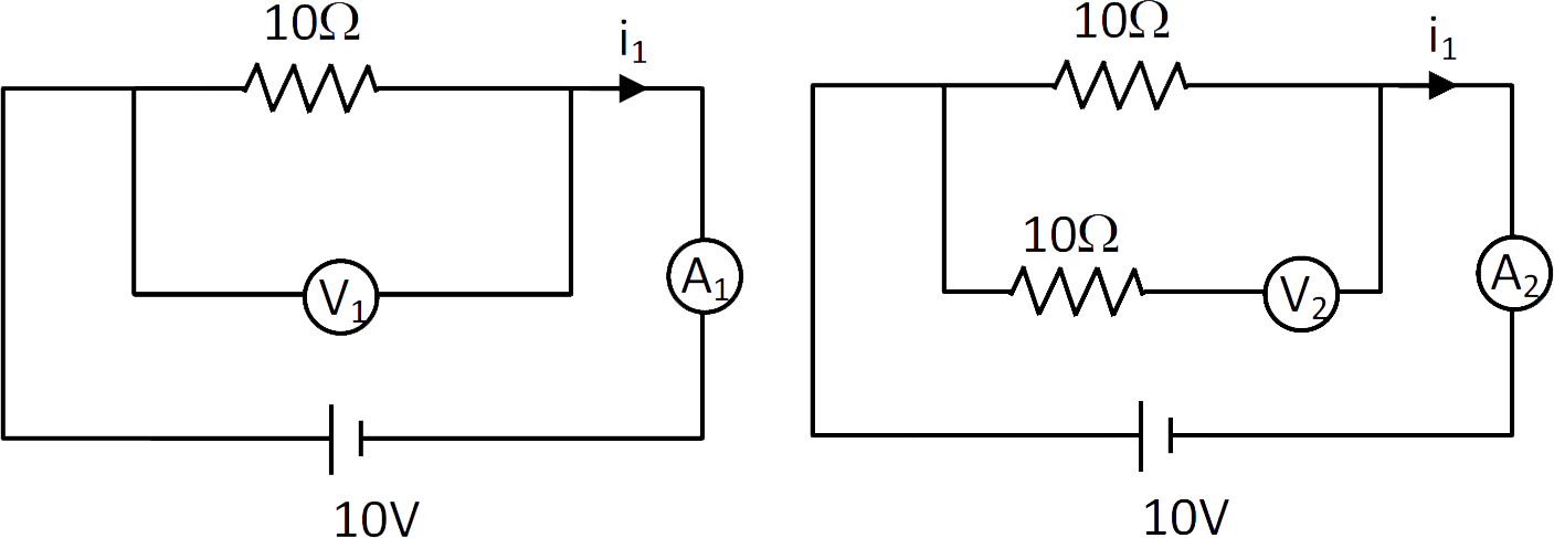
View SolutionIn the circuit shown in Fig. 6.50, an idel ammeter and an ideal voltmeter are used. Whan the key is open, the voltmeter reads 1.53V. When the key is closed, the ammeter reads 1.0A and the voltmeter reads 1.03V. The resistance R is

View Solution
Assertion : In the circuit shown in figure ammeter and voltmeter are non-ideal when positions of ammeter and voltmeter are changed, reading of ammeter will increase while of voltmeter will decrease.
Reason : Resistance of an ideal ammeter is zero while that of an ideal voltmeter is infinite.
View Solution