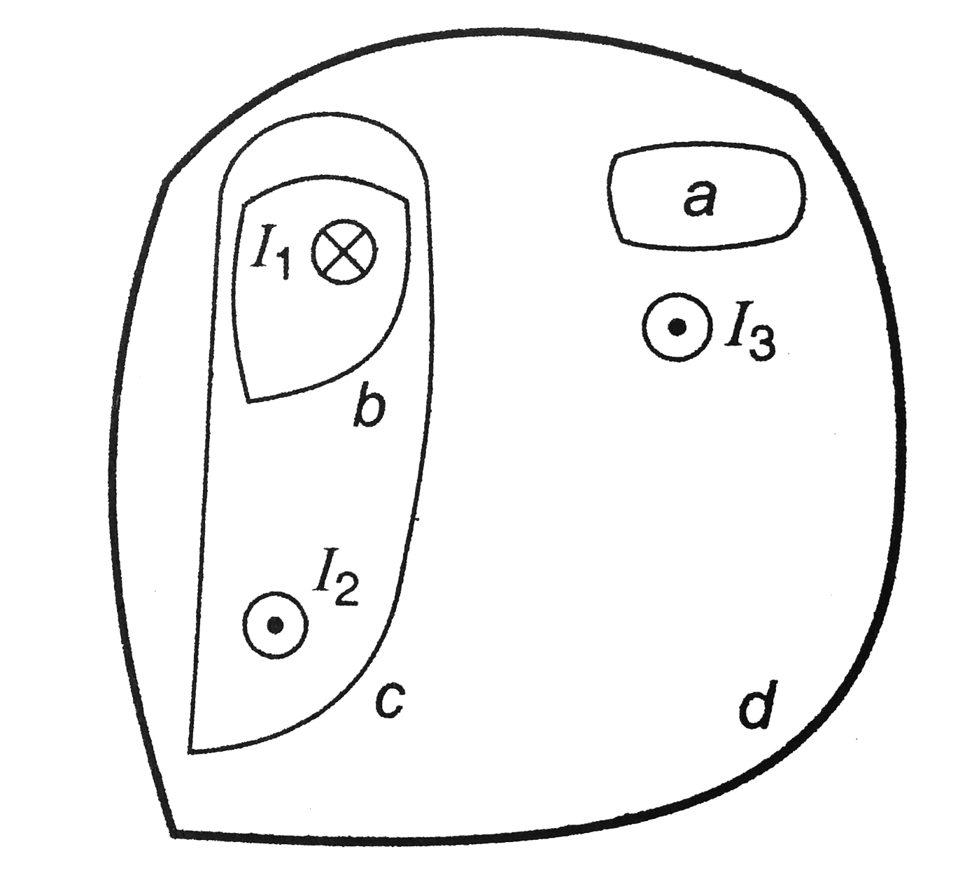
Figure shows, in cross-section, several conductors that carry currents through the plane of the figure. The currents have the magnitudes i1=4.0A,I2=6.0A, and I3=2.0 A, in the directions shown. Four paths labelled a to d, are shown. What is the line integral ∫B.dI for each path? Each integral involves going around the path in the counter-clockwise direction.
∫B.I=μ(inet)
Along path as net current enclosed by this path is zer.
Hence line integral =0
along path b inetis(ox). So, magnetic lines along this current is clockwise. But, we have to take line integral in counter clockwise direction. Hence, line integral will be negative.
Topper's Solved these Questions
- MAGNETICSBOOK - DC PANDEY ENGLISHCHAPTER - MAGNETICSEXERCISE - SCQ_TYPE
5 Videos
- MAGNETICSBOOK - DC PANDEY ENGLISHCHAPTER - MAGNETICSEXERCISE - MCQ_TYPE
1 Videos
- MAGNETICSBOOK - DC PANDEY ENGLISHCHAPTER - MAGNETICSEXERCISE - SUBJECTIVE_TYPE
1 Videos
- MAGNETIC FIELD AND FORCESBOOK - DC PANDEY ENGLISHCHAPTER - MAGNETIC FIELD AND FORCESEXERCISE - Medical entrance s gallery
59 Videos
- MAGNETISM AND MATTERBOOK - DC PANDEY ENGLISHCHAPTER - MAGNETISM AND MATTEREXERCISE - Medical gallery
1 Videos
Similar Questions
Figure shows a cross-section of a long ribbon of width ω that is carrying a uniformly distributed total current i into the page. Calculate the magnitude and direction of the magnetic field B at a point P in the plane of the ribbon at a distance d from its edge.

View SolutionA thin rod, carrying current i2 is placed near a long straight wire carrying current i1 in the plane of rod as shown in figure. The motion of rod is
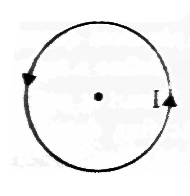
View SolutionIn figure is shown a circular loop carrying current I. Show the direction of the magnetic field with the help of lines of force.
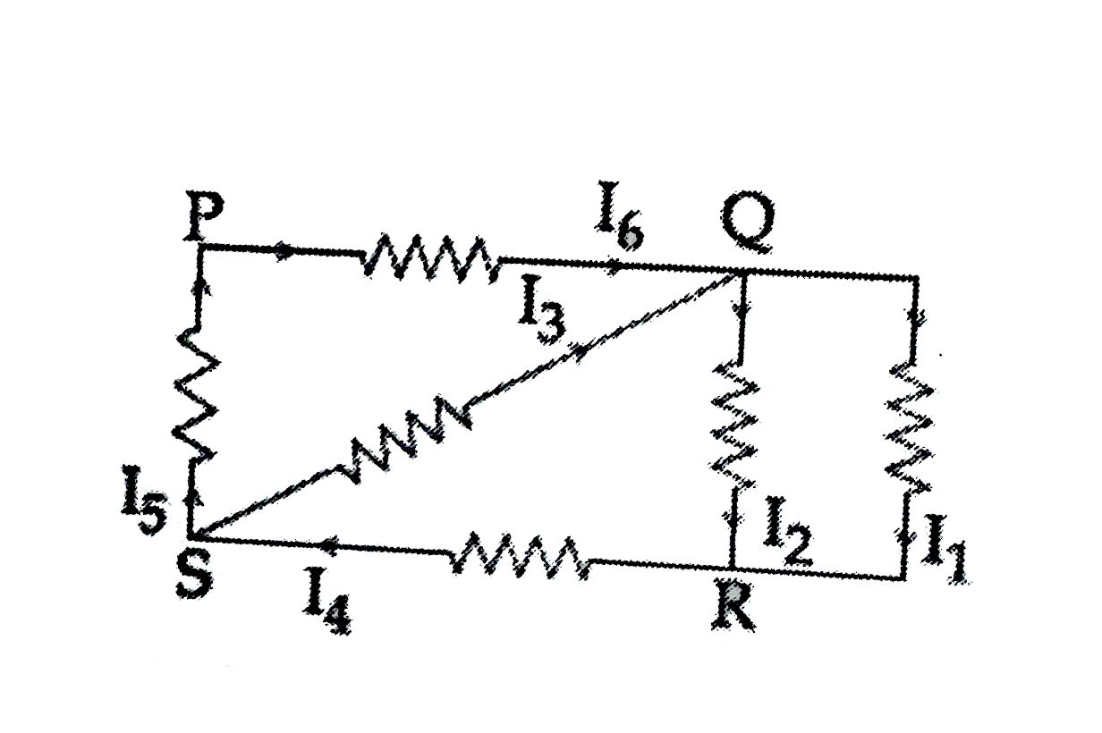
View SolutionIn the given circuit diagram, the currents, I1=−0.3A,I4=0.8A and I5=0.4A, are flowing as shown. The currents I2,I3 and I6 respectively, are :
View SolutionFigure. Shows two long wires carrying equal currents I1andI2 flowing in opposite directions. Which of the arrows labeled A to D correctely represents the direction of the magnetic field due to the wires at a point located at an equal distance d from each wire?
View SolutionFigure shows an end view of two long, parallel wires perpendicular to the xy plane, each carrying a current I, but in opposite directions.
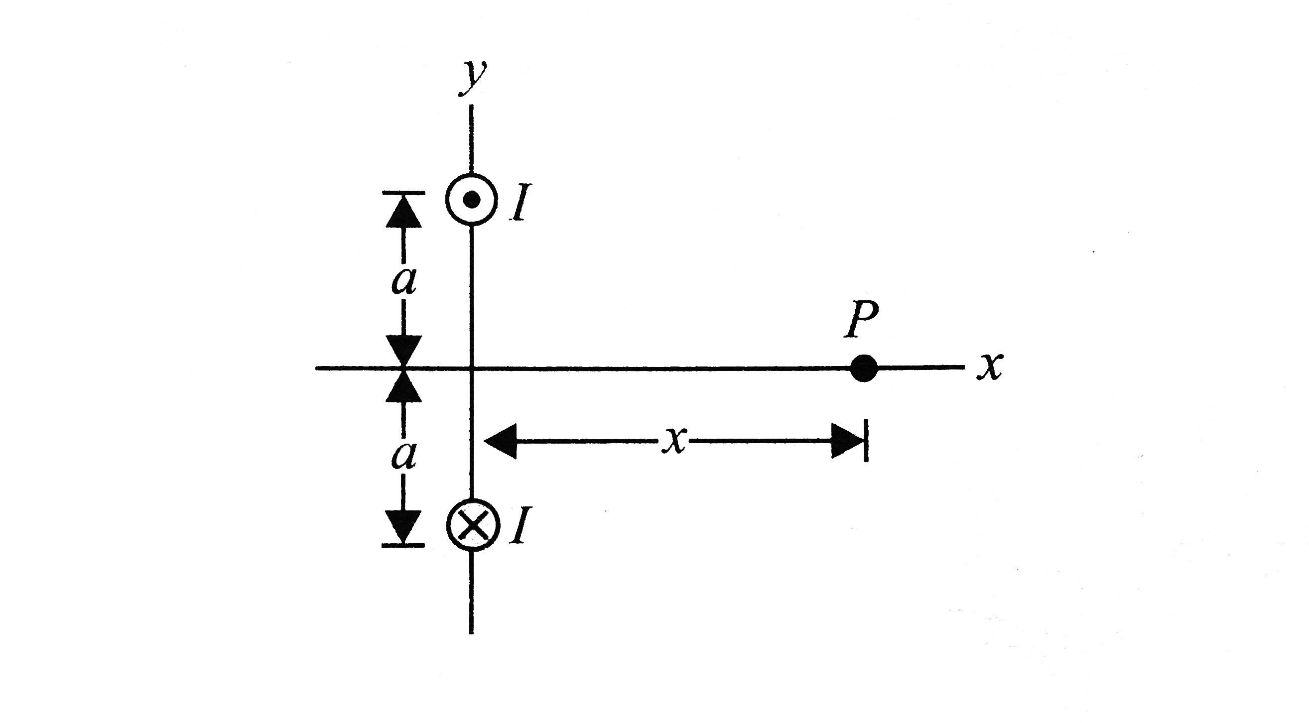
Graph the magnitude of →B at point on the x-axis.
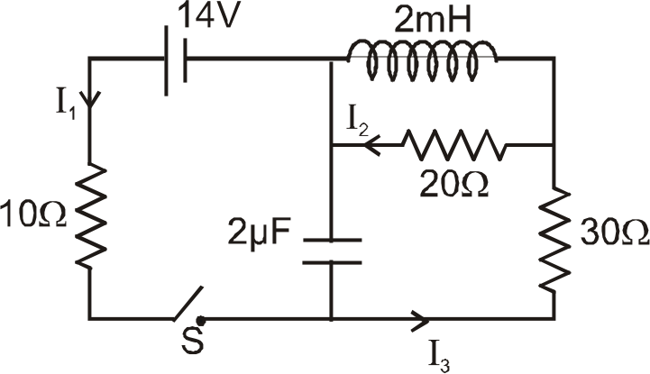
View SolutionIn the circuit shown, the switch is closed at t=0, the currents I1,I2 and I3 are
View SolutionTwo very long straight , and insulated wires are Kept at 90∘ angle from each other in xy-plane as shown in the figure.
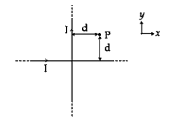 These wires carry current of equal magnitude I, whose direction are shown in the figure The net magnetic field at point P will be:
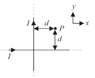
View SolutionTwo very long, straight, and insulated wires are kept at 90∘ angle from each other in xy-plane as shown in the figure. These wires carry currents of equal magnitude I, whose directions are shown in the figure. The net magnetic field at point will be:
View SolutionFigure shows an end view of two long, parallel wires perpendicular to the xy plane, each carrying a current I, but in opposite directions.
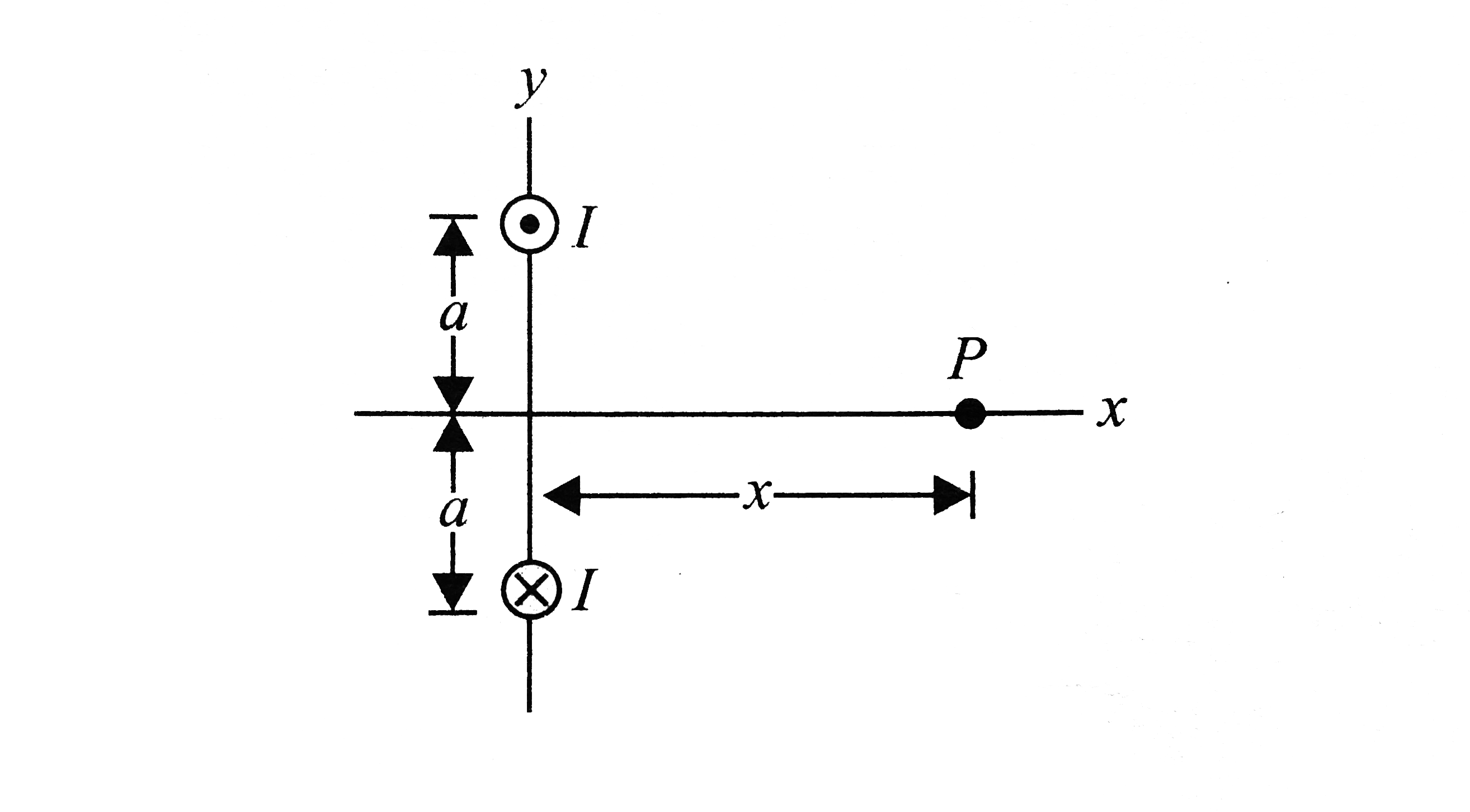
Derive an expression for the magnitude of →B at any point on the x-axis in terms of the x-coordinate of the point. What is the direction of →B?
View Solution
