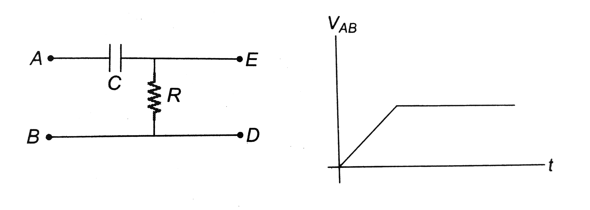
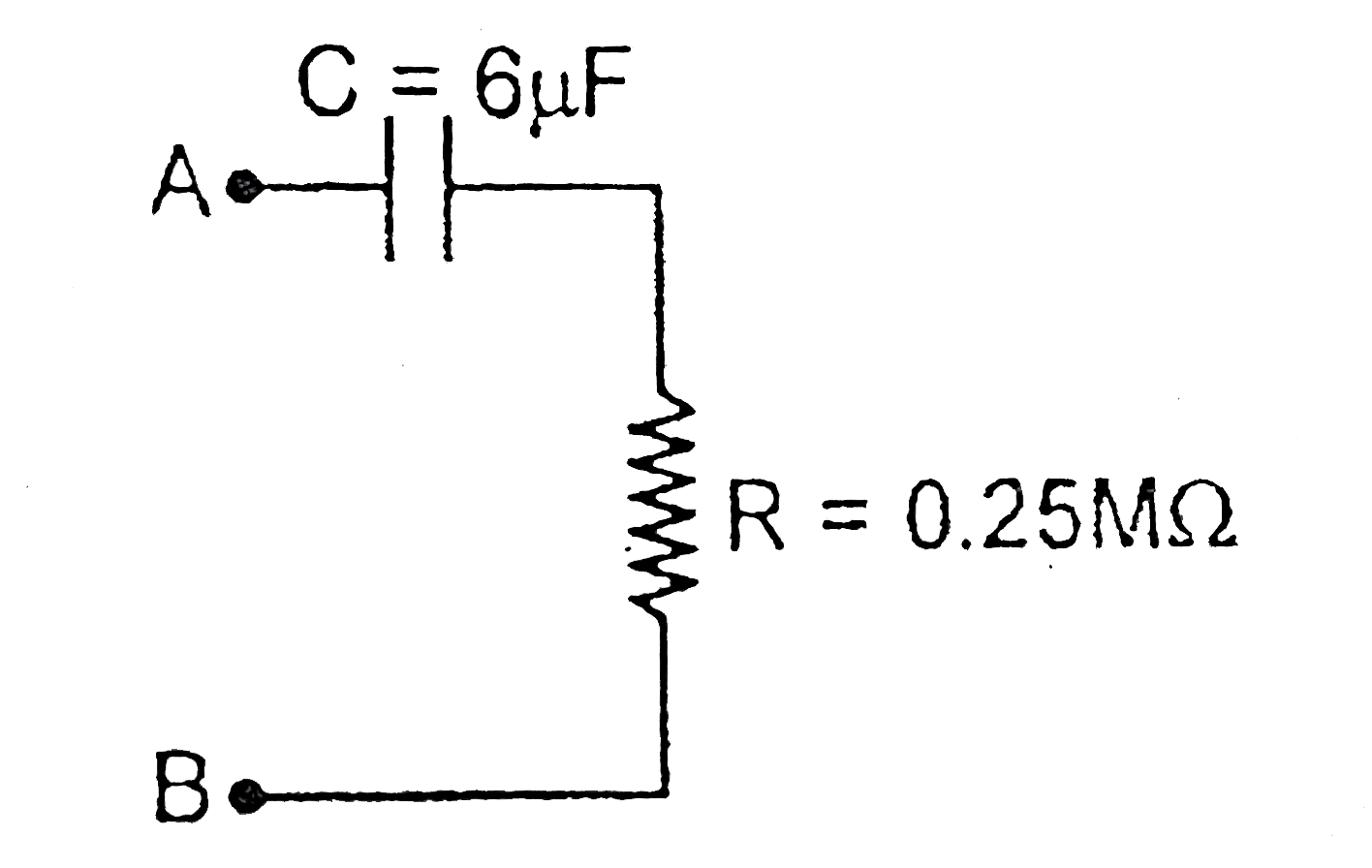
A time varying voltage is applied to the clamps A and B such that voltage across the capacitor plates is as shown in the figure. Plot the time dependence of voltage across the terminals of the esistance E and D.
The correct Answer is:A
From O to A
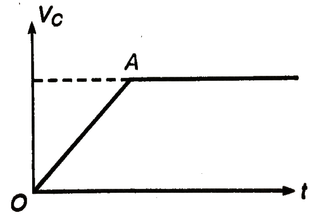
. VC=at(a=constant)
∴qC=CVC=Cat
∴i=dqCdt=aC
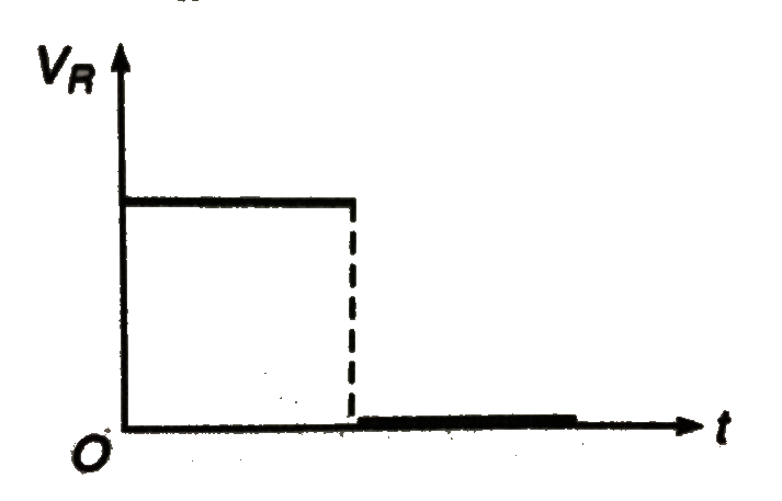
VR=iR+aCr=constant
From A onwards VC=(constant)
∴qconstant
∴i=dqcdt=0
or Vr=0
Therefore VR versus t graph is as showin in figure
Topper's Solved these Questions
- CAPACITORSBook:DC PANDEY ENGLISHChapter:CAPACITORSExercise:OBJECTIVE_TYPE
Explore 1 Video
- CAPACITORSBook:DC PANDEY ENGLISHChapter:CAPACITORSExercise:OBJECTIVE_TYPE
Explore 1 Video
- ATOMSBook:DC PANDEY ENGLISHChapter:ATOMSExercise:MEDICAL ENTRANCES GALLERY
Explore 42 Videos
- COMMUNICATION SYSTEMBook:DC PANDEY ENGLISHChapter:COMMUNICATION SYSTEMExercise:Subjective
Explore 11 Videos
Similar Questions
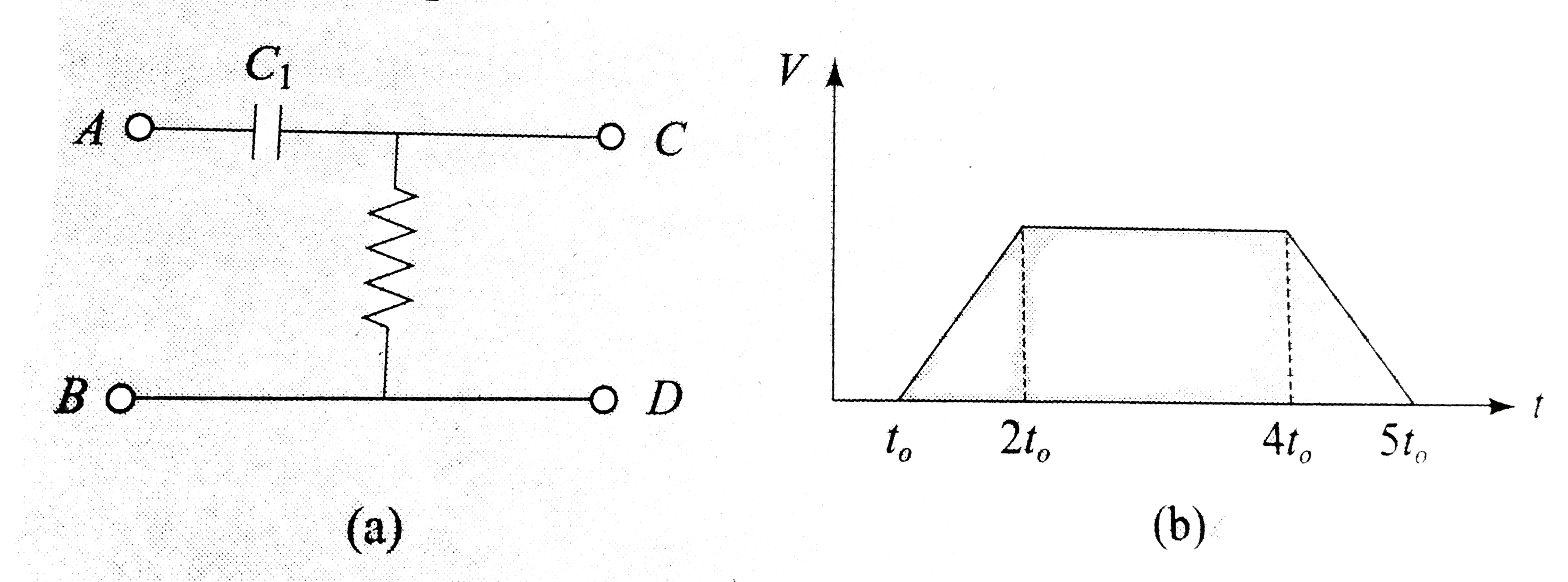
A varying voltage is applied to the clamps AB as shown in fig. such that the voltage across the capacitor plates varies as shown in the figure. Plot the time depending on voltage across the clapes CD.

View SolutionA time varying voltage is applied across A & B such that voltage across capacitor is given by VC=2sin2t. What is maximum potential difference across the reistance?
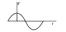
View SolutionVoltage across a capacitor varies as shown in the diagram. Which diagram correctly represents the current time curve?
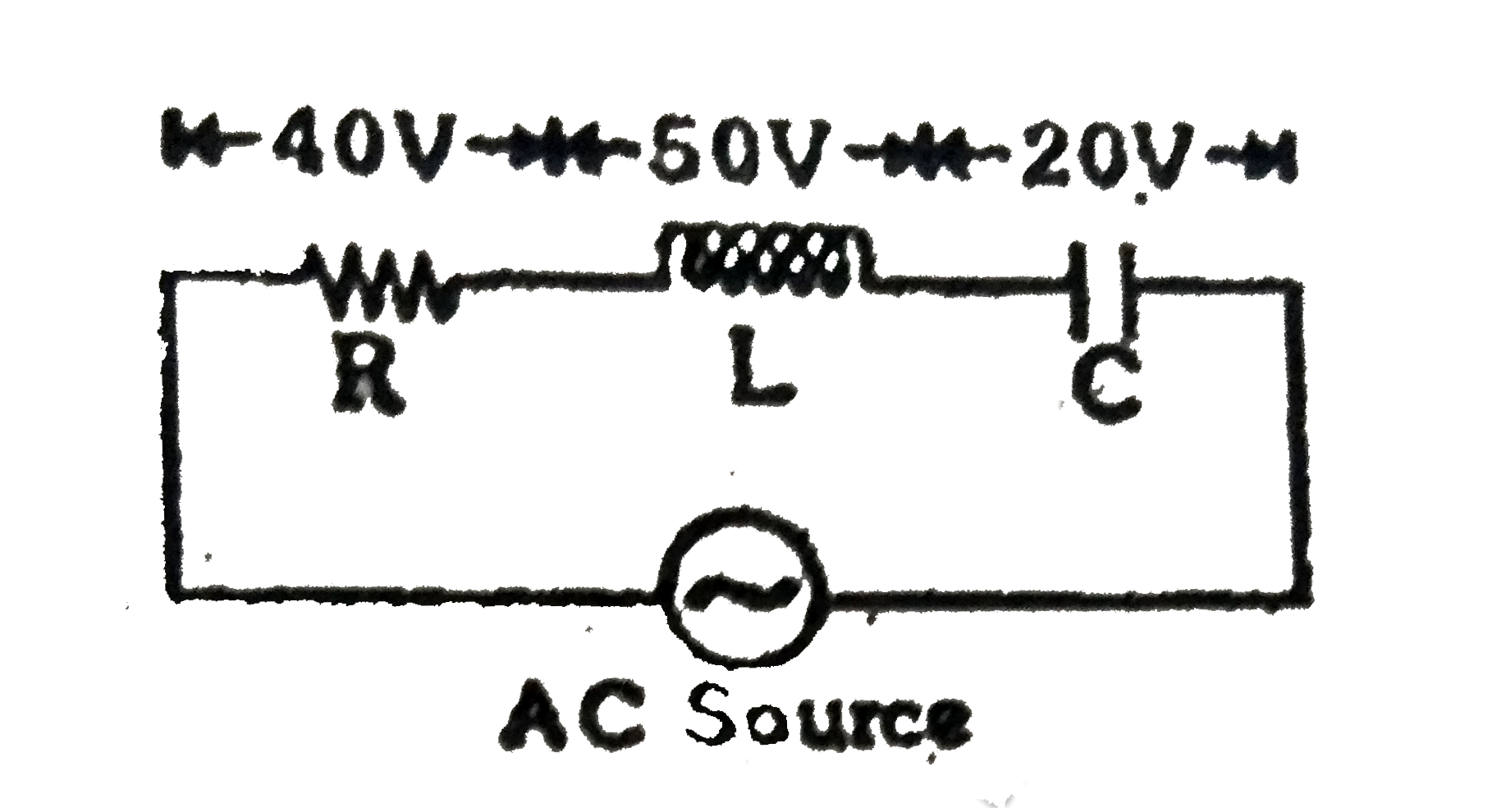
View SolutionIn series LCR circuit, the voltages across R, L and C are shown in the figure. The voltage of applied source
View SolutionFor the circuit shown in figure, determine the voltage across 4Ω resistors in volt ?

View SolutionAC voltage source (V,ω) is applied across a parallel LC circuit as shown in figure. Find the impedance of the circuit and phase of current.

View SolutionA 1μF capacitor and a 2µF capacitor are connected in series across a 1200V supply line.
a. Find the charge on each capacitor and the voltage across them.
b. The charged capacitors are disconnected from the line and from each other and reconnected with terminals of like sign together. Find the final charge on each and the voltage across them.
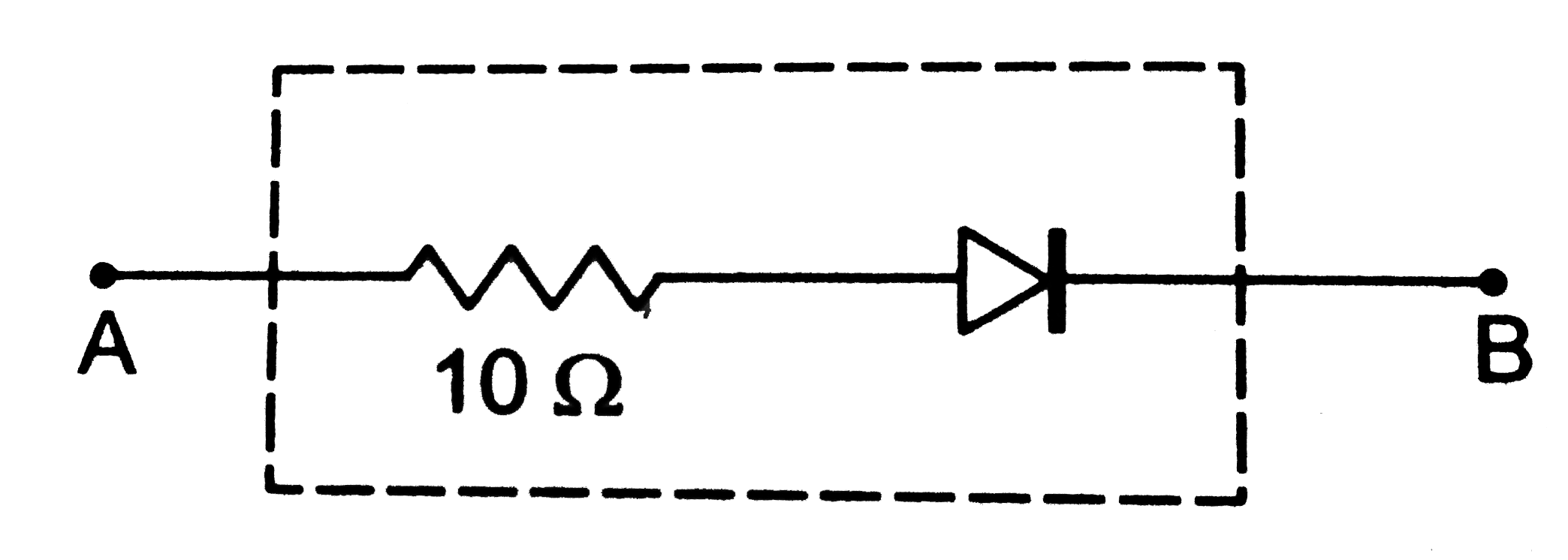
View SolutionDraw the current-voltage characteristics for the device shown in figure between the terminal A and B.

View SolutionAn AC voltage is applied acrss a series combination of L and R. If the voltage drop across the resistor and inductor are 20V and 15V respectiely, then applied peak voltage is
View Solution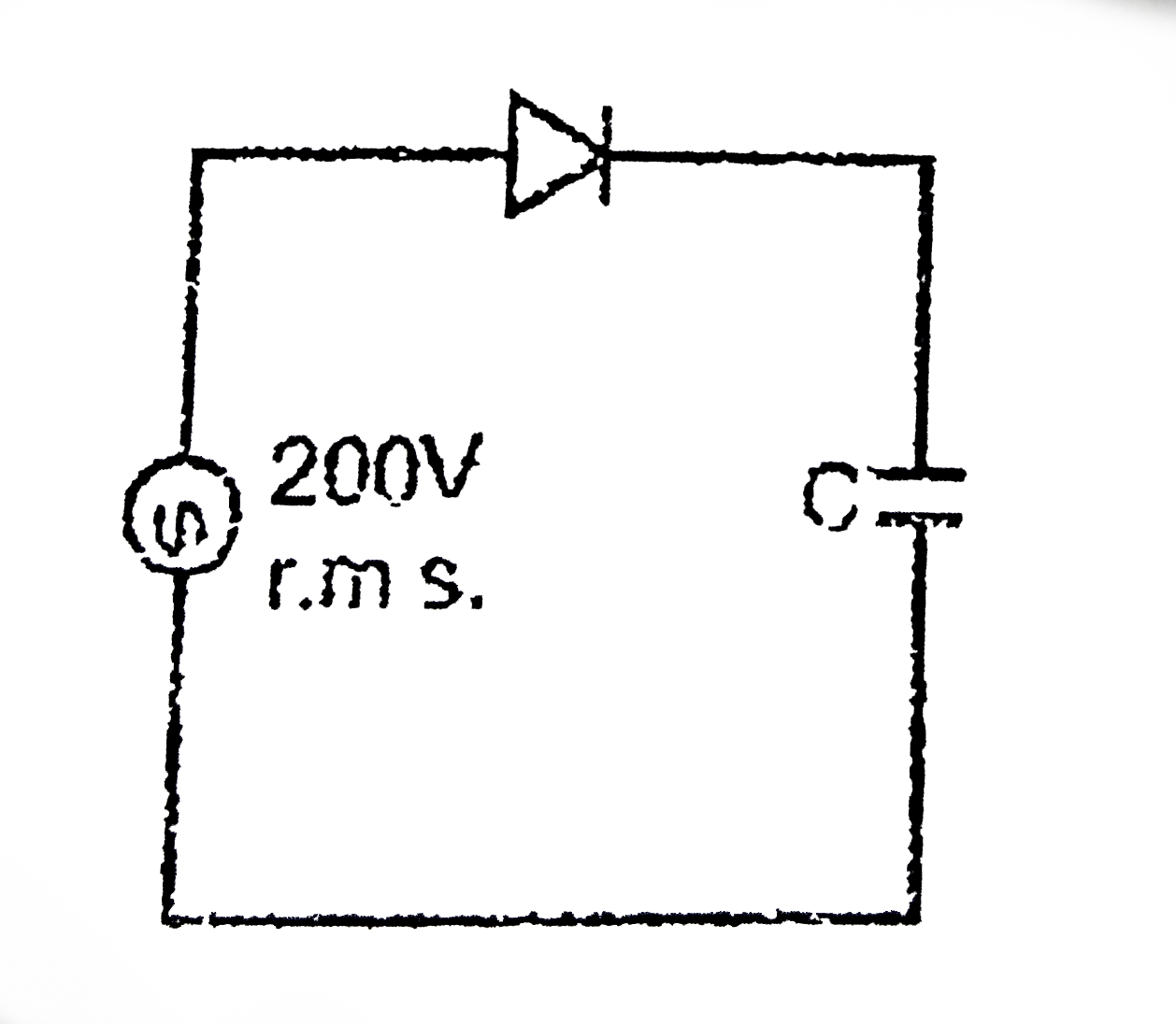
In the figure an A.C of rms voltage 200 volt is appled to the circuit containing diode and the capacitor and it is being rectified. The maximum potential across the capacitor C in volt will be
View Solution
