In the circuit shown, A and B are equal resistances. When S is closed, the capcitor Ccharges from the cell of emf epsilon and reaches a steady state.
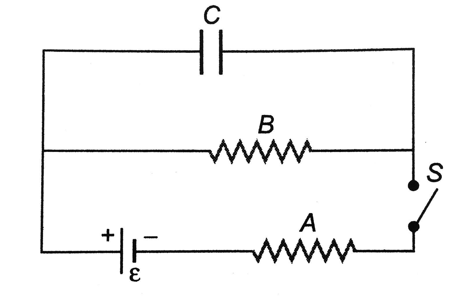
During charging, more heat is produced in A than in B
In stedy state heat is produced at the same rate in A and B
In the steady state, energy stored in C is 14Cε2
In the steady state energy stored in C is 18Cε2
The correct Answer is:A, B, D
Current through A is the main current passing through the battery. So, the current is more than the current passing through B. Hence, during charging more heat is produced is A.
In steady state
iC=0
andiA=iB
Hence, heat is produced at the same rate in A and B.
further, in steady state
VC=VB=ε2
∴U=12CV2C=18Cε2
Topper's Solved these Questions
- CAPACITORSBOOK - DC PANDEY ENGLISHCHAPTER - CAPACITORSEXERCISE - OBJECTIVE_TYPE
1 Videos
- CAPACITORSBOOK - DC PANDEY ENGLISHCHAPTER - CAPACITORSEXERCISE - OBJECTIVE_TYPE
1 Videos
- ATOMSBOOK - DC PANDEY ENGLISHCHAPTER - ATOMSEXERCISE - MEDICAL ENTRANCES GALLERY
42 Videos
- COMMUNICATION SYSTEMBOOK - DC PANDEY ENGLISHCHAPTER - COMMUNICATION SYSTEMEXERCISE - Subjective
11 Videos
Similar Questions
Initially the circuit is in steady state. When the switch S is closed, the heat generated in the circuit will be

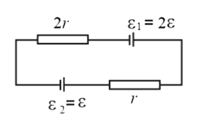
View SolutionIn the circuit shown if the internal resistance of each cell is r, then the rate at which the chemical energy of ε1 is being consumed is
View SolutionIn the circuit shown, the resistances are given in ohms and the battery is assumed ideal with emf equal to 3.0 V.
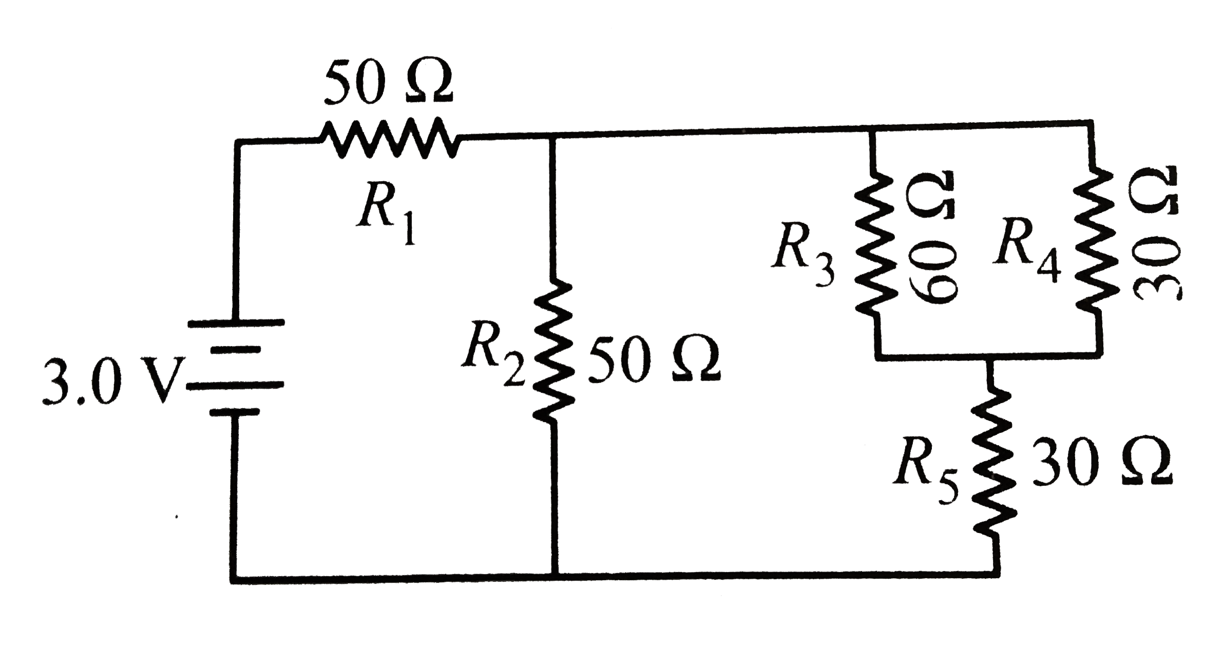
View SolutionIn the circuit shown in the figure, in steady state:
The current drawn from the battery is
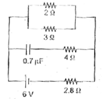
View SolutionIn the circuit shown , the internal resistance of the cell is negligible . The steady stale current in the 2Ω resistor is
View Solution
In the circuit shown below, the internal resistance of the cell is negligible. The distance of the slider from the left-hand end of the slide wire is l. The graph shows the variation with l of the current I in the cell.
E.M.F. of the cell is:
View SolutionIn the circuit shown in figure switch S is closed at time t=0
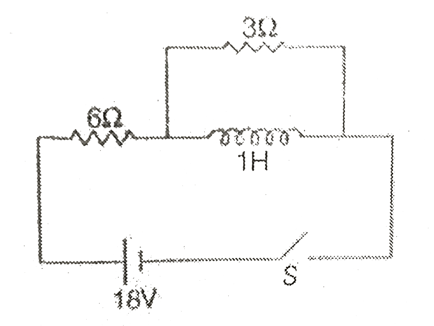
At what time current through 3Ω resistance and 1H inductor are equal?
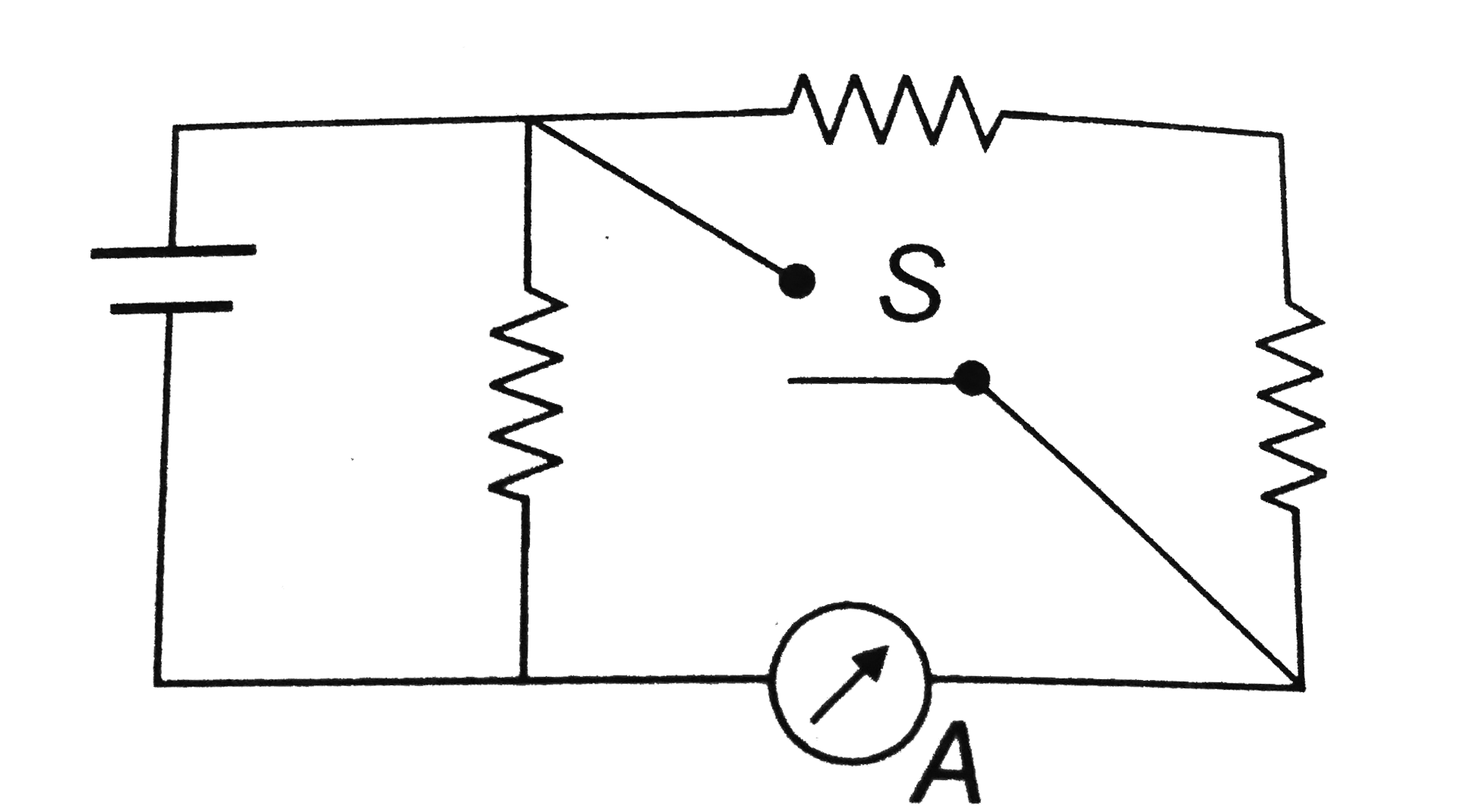
View SolutionIn the circuit shown, the reading of the Ammter is doulbed after the switch is closed. Each resistor has a resistance =1Ω and the ideal cell has an e.m.f. =10V. Then the ammeter has a resistance equal to
View SolutionIn the figure the potentiometer wire AB of length L and resistance 9 r is joined to the cell D of e.m.f ε and internal resistance r. The emf of cell C is ε2 and its internal resistance is 2r.The galvanometer G will show on deflection when the length AJ is
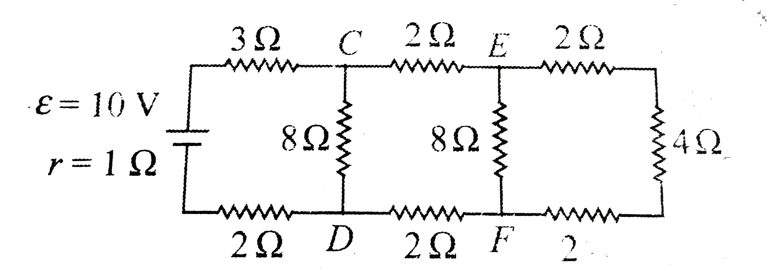
View SolutionIn the circuit shown in fig. the cell has emf 10V and internal resistance 1Ω
View Solution

