An electrical circuit is shown in the given figure. The resistance of each voltmeter is infinite and ech ammeter is 100Ω. The charge on the cpacitor of 100μF in steady staste is 4mC. Chose correct statement(s) regarding the given circuit.
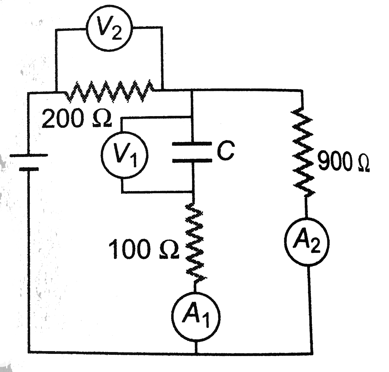
Reading of voltmeter V2is16
Reading of ammeter A1 is zero and A2 is 125A
Reading of voltmeter V1 is 40V
Emf of the ideal cell is 66V
The correct Answer is:B, C, D
In steady state current through capacitor wire is zero. Current flows 200Ω,900Ω and A2.
VC=qC=4×10−3100×10−6
=40V
This is also potential drop across 900Ω resistance and 100Ω ammeter A2 (Total resistance =1000Ω). Now, this 1000Ω and 200Ω are in series. Therfore,
V2=V200Ω=V1000Ω5
405=8V
Emf=V1000Ω+V200Ω=48V
i=EmfNet resistance
=481200=125A
Topper's Solved these Questions
- CAPACITORSBOOK - DC PANDEY ENGLISHCHAPTER - CAPACITORSEXERCISE - OBJECTIVE_TYPE
1 Video
- CAPACITORSBOOK - DC PANDEY ENGLISHCHAPTER - CAPACITORSEXERCISE - OBJECTIVE_TYPE
1 Video
- ATOMSBOOK - DC PANDEY ENGLISHCHAPTER - ATOMSEXERCISE - MEDICAL ENTRANCES GALLERY
42 Videos
- COMMUNICATION SYSTEMBOOK - DC PANDEY ENGLISHCHAPTER - COMMUNICATION SYSTEMEXERCISE - Subjective
11 Videos
Similar Questions
The charge across the capacitor in two different RC circuit 1 and 2 are potted as shown in figure.
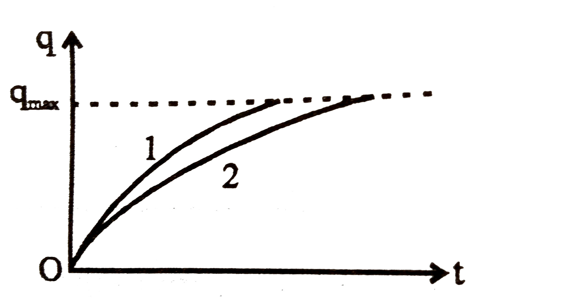
Choose the correct statement (s) related to the two circuit.
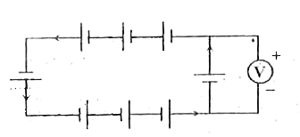
View Solutionin the circuit shown in the figure, each battery is of 5 V and has an internal resistance of 0.2 Omega What is the reading of the ideal voltmeter V
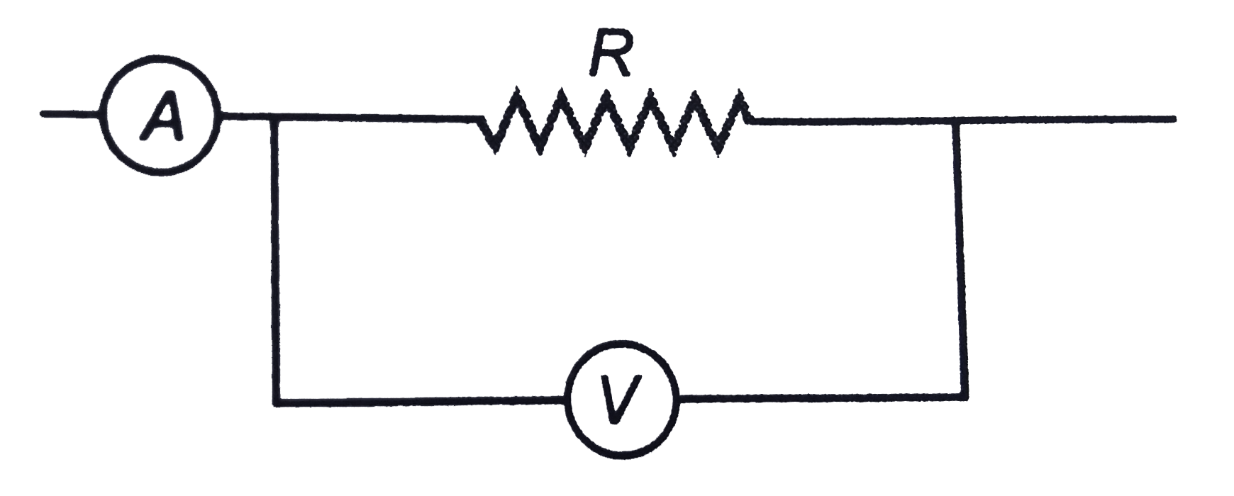
View SolutionA part of a circuit is shown in figure. Here reading of ammeter is 5A and voltmeter is 100V. If voltmeter resistance is 2500ohm, then the resistance R is approximately
View SolutionConsider the potentiomter circuit diagram as shown in the figure. If the potentiometer wire BD has net resistance of 15Omega, the choose the correct statement
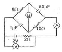
_PHY_E01_009_Q01.png)
View SolutionThe ammeter (A) and voltmeter (V) in the given circuit are ideal but the galvanometer has a resistance of 2Ω In steady state
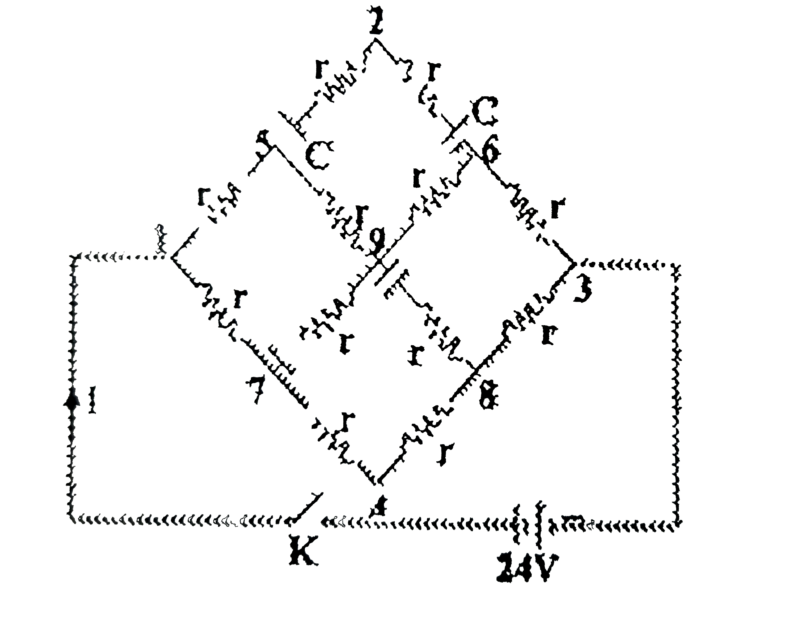
View SolutionIn the circuit shown, r=4Ω, C=2μF
(a) Find the current coming out of the battery just after the switch is closed.
(b) Find charge on each capacitor in the steady state condition.
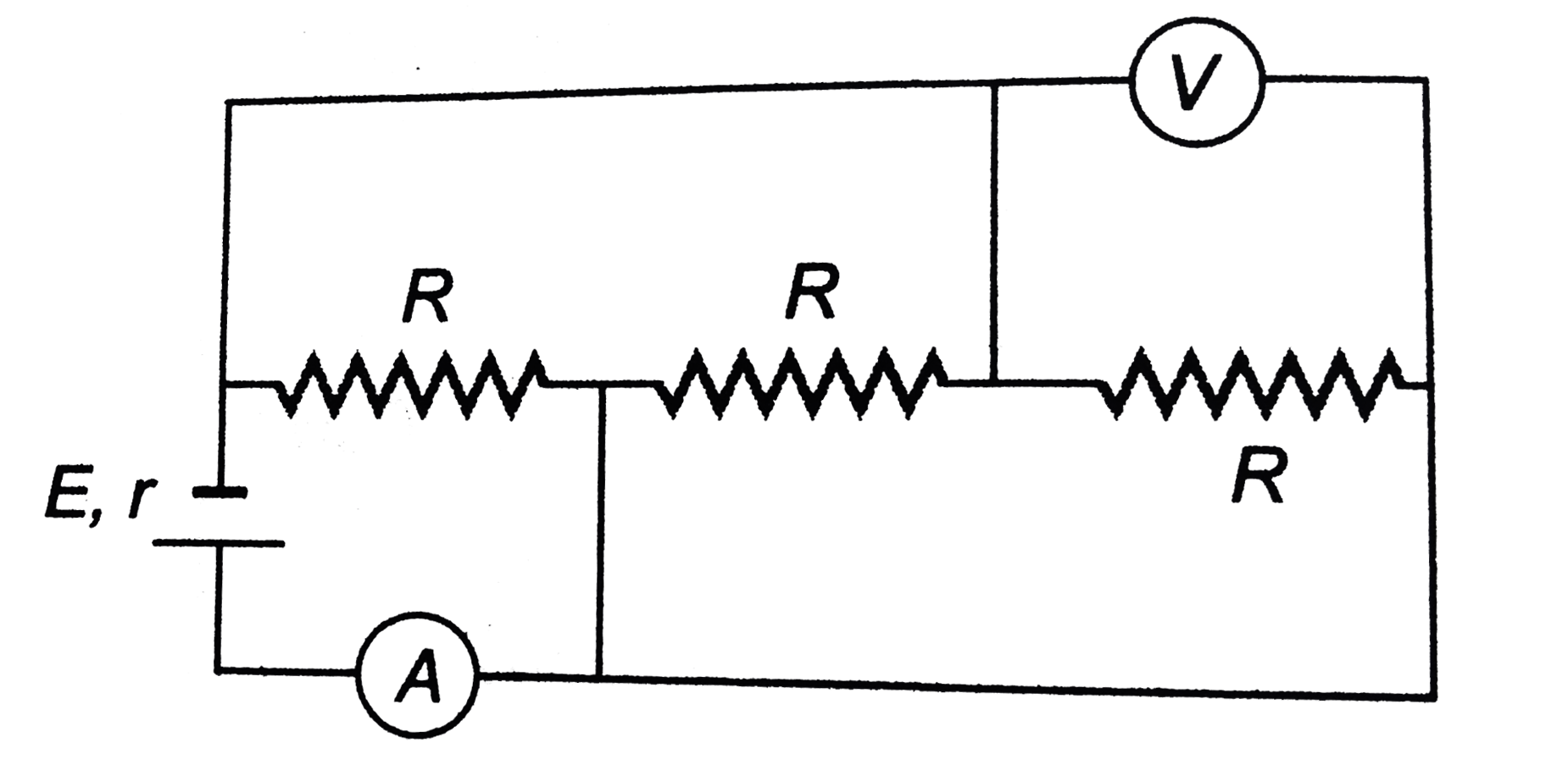
View SolutionIn the circuit shown in figure ammeter and voltmeter are ideal. If E=4V,R=9Ω and r=1Ω then readings of ammeter and voltmeter are
View SolutionIn the circuit shown in figure ammeter and voltmeter are ideal. If E=4V,R=9Ω and r=1Ω then readings of ammeter and voltmeter are

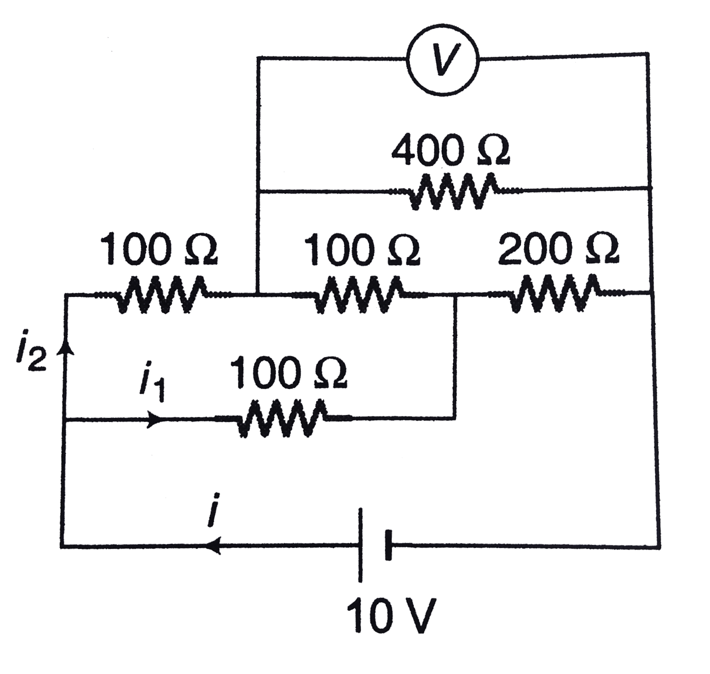
View SolutionAn electrical circuit is shown in figure. Calculate the potential difference across the resistor of 400Ω as will be measured by the voltmeter Vof resistance 400Ω either by applying Kirchhoff's rules or otherwise.
View SolutionIn an RLC series circuit shown in fig. the reading of voltmeters (V1)and(V2) are 100 V and 200 V respectively. The source voltage is 130 V. for this situation, mark out the correct statements (s).
View Solution
