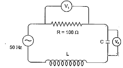
In an RLC series circuit shown in fig. the reading of voltmeters (V1)and(V2) are 100 V and 200 V respectively. The source voltage is 130 V. for this situation, mark out the correct statements (s).
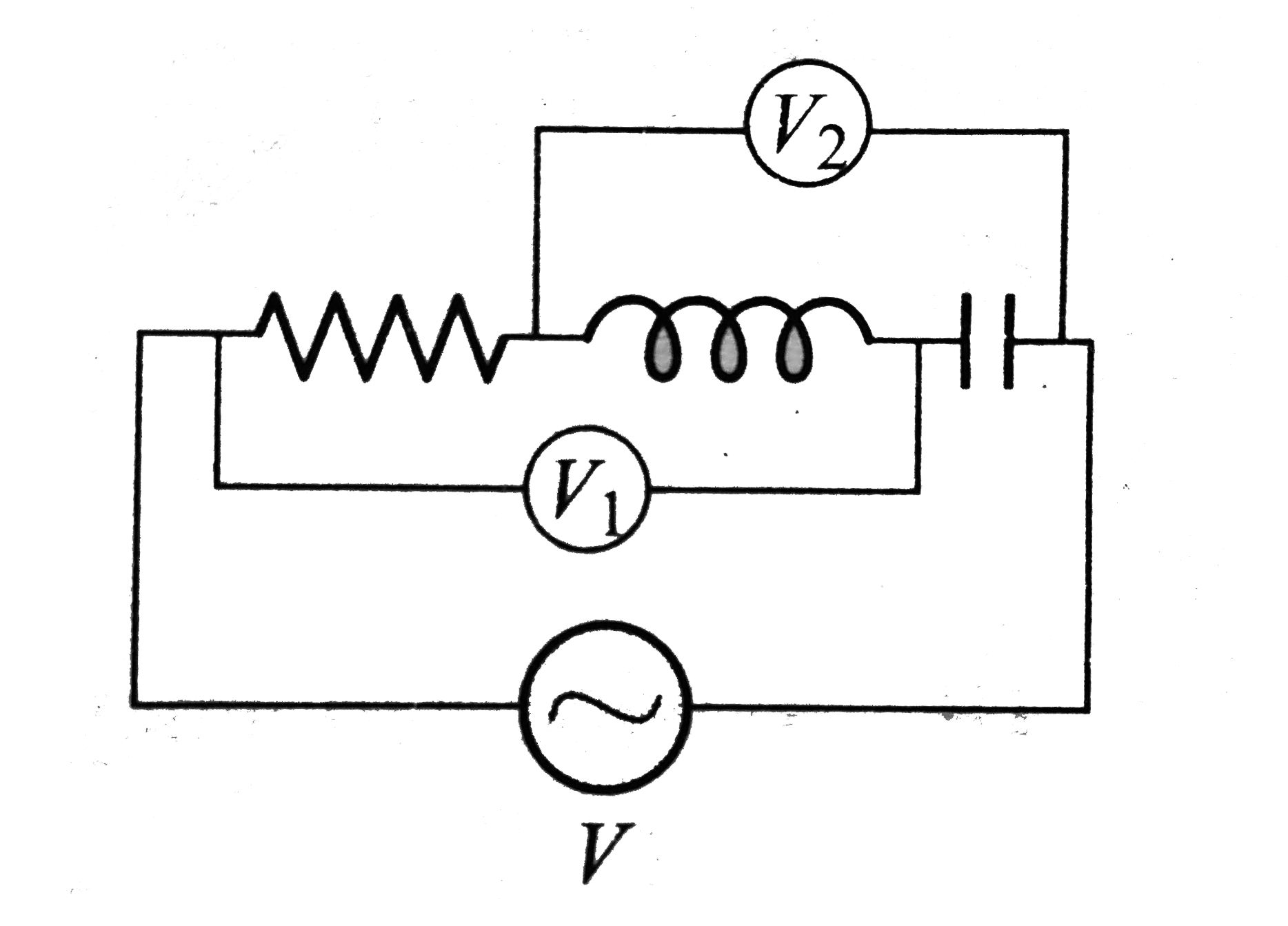
Voltage across resistor inductor and capacitor are 50 V 50√3V, and120+50√3 V, respectively
Voltage across resistor inductor and capacitor are 50 V 50√3V, and 120−50√3V, respectively
Power factor of the corcuit is 513
The circuit is capactive in nature
The correct Answer is:A, C, D
V2R+V2L=1002,|VC−VL|=120
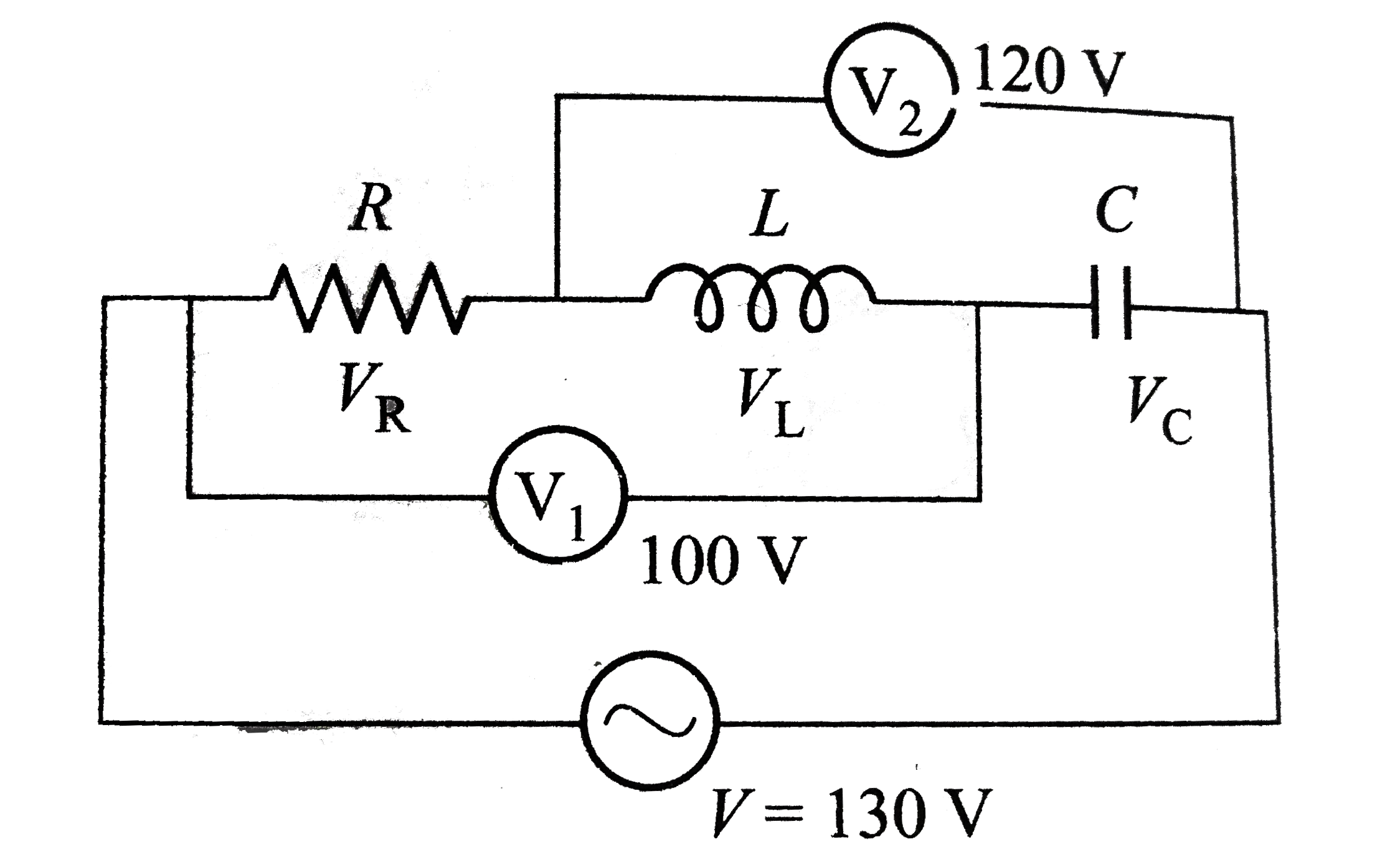
1302=V2R+(VC−C2L⇒VR=50V
⇒(VL)=√1002−502=50√3V
VC=120+50√3V
cosϕ=VRV=50130=513
Since (VC)<(VL), so circuit is capacitive.
Topper's Solved these Questions
- ALTERNATING CURRENTBOOK - CENGAGE PHYSICS ENGLISHCHAPTER - ALTERNATING CURRENTEXERCISE - Exercises Assertion-reasoning
7 Videos
- ALTERNATING CURRENTBOOK - CENGAGE PHYSICS ENGLISHCHAPTER - ALTERNATING CURRENTEXERCISE - Exercises Linked Comprehension
25 Videos
- ALTERNATING CURRENTBOOK - CENGAGE PHYSICS ENGLISHCHAPTER - ALTERNATING CURRENTEXERCISE - Exercises Single Correct
63 Videos
- ATOMIC PHYSICSBOOK - CENGAGE PHYSICS ENGLISHCHAPTER - ATOMIC PHYSICSEXERCISE - ddp.4.3
15 Videos
Similar Questions
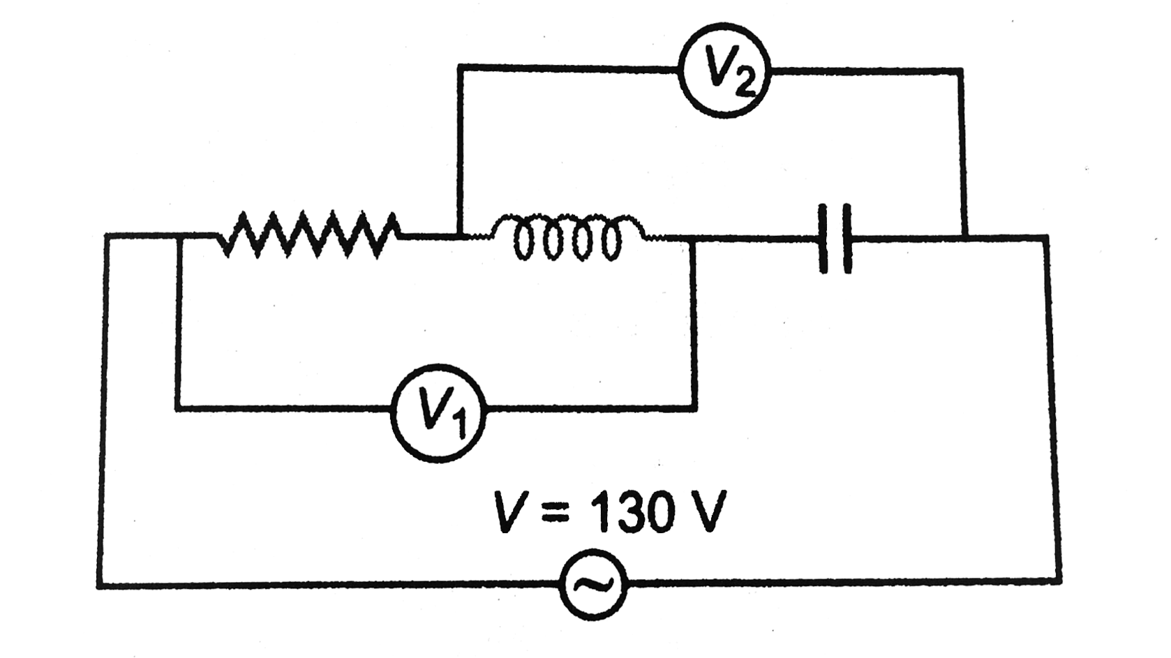
In a R−L−C series circuit shown in readings of voltmeters V1 and V2 are 100V and 120V.
Choose the corredct statement(s).
 .
.
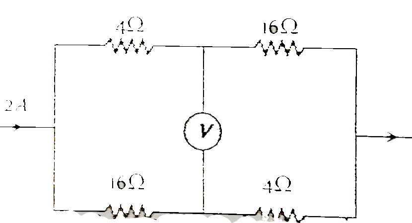
View SolutionIn the circuit shown below. The reading of the voltmeter V is
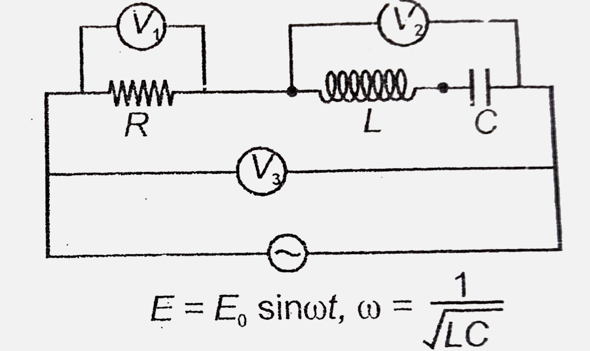
View SolutionIn the circuit shown, the readings of voltmeters V1,V2andV3 are given by
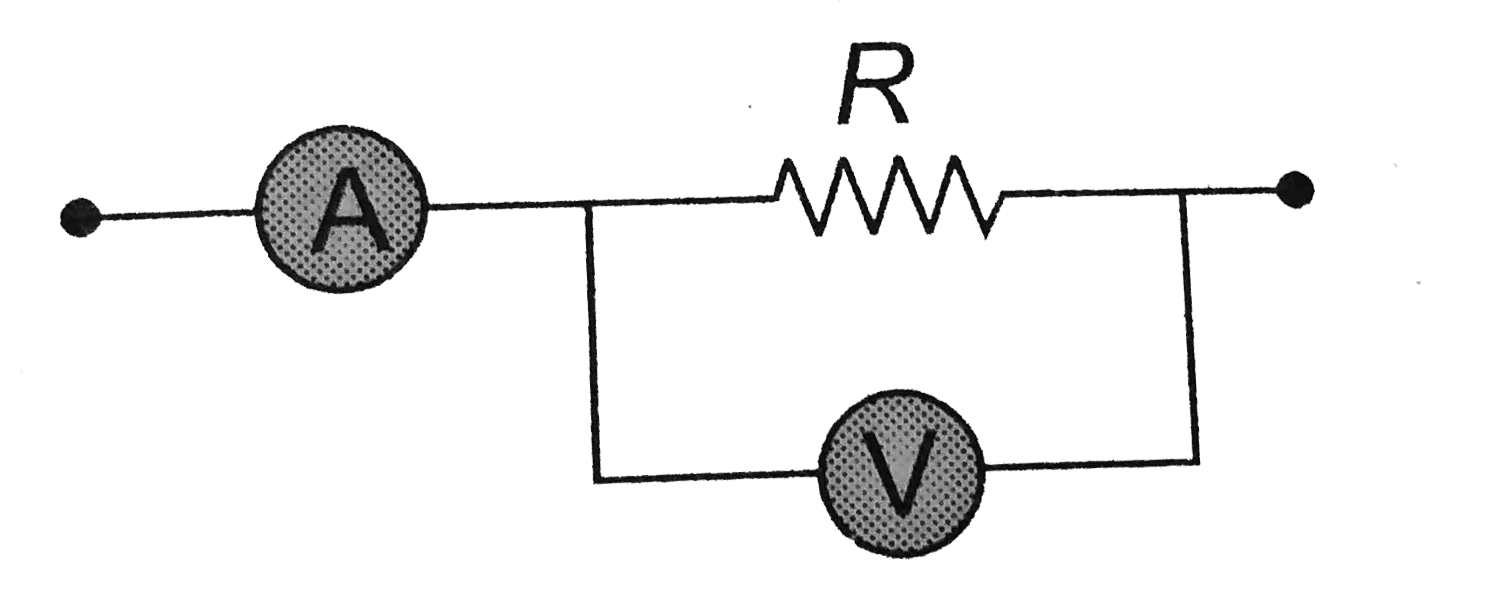
View SolutionIn the circuit shown the reading of ammeter and voltmeter are 4A and 20V respectively. The meters are non ideal, then R ia
View SolutionIn an LCR series ac circuit the voltage across L,C and R are V1,V2 and V3 respectively The voltage of the source is .
View SolutionIn an LCR series circuit, the reading of ideal voltmeters V1 and V2 are 20√2 volt and 15 volts respectively as shown in the figure (the given circuit in inductive in nature). Then
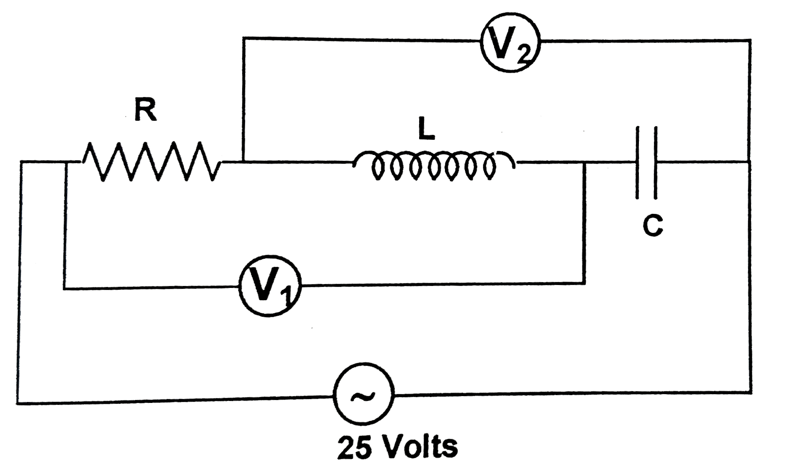
View SolutionConsider the circuit shown in the figure, the cell is ideal. The readings of the ideal voltmeters V1 and V2 in volts are respectively.

View Solution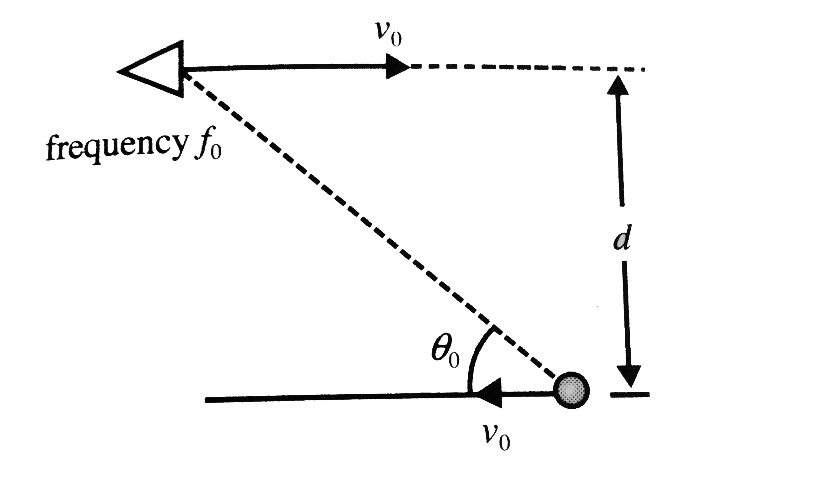
A source of sound and detector are moving as shown in Fig. at t=0. Take velocity of sound wave to be v. For this situation mark out the correct statement(s).
View Solution
A source of sound and detector are moving as shown in Fig. at t=0. Take velocity of sound wave to be v. For this situation mark out the correct statement(s).
View SolutionFollowing figure 6 shows a series RCL circuit connected to an ac source which generates an alternating emf of frequency 50 Hz. The readings of the voltmeters V1 and V2 are 80 V and 60 V respectively.
(1) the current in the circuit.
(2) the capacitance of the capacitor.
(ii) At resonance, what is the relation between impedance of a series LCR circuit and its resistance R?
View Solution
