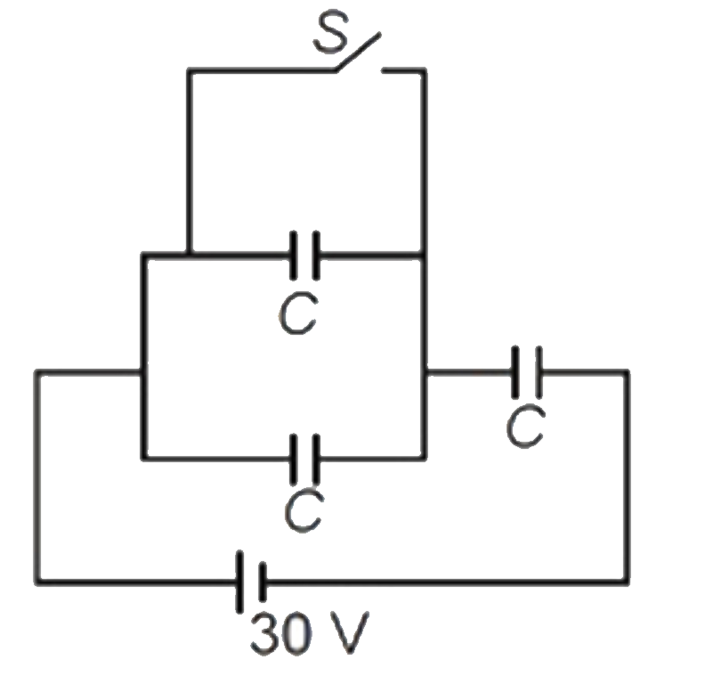
Initially the circuit is in steady state. When the switch S is closed, the heat generated in the circuit will be

ε2C2
2ε2C
3ε2C2
Zero
The correct Answer is:D
Step by step video & image solution for Initially the circuit is in steady state. When the switch S is closed, the heat generated in the circuit will be by Physics experts to help you in doubts & scoring excellent marks in Class 12 exams.
Updated on:21/07/2023Topper's Solved these Questions
- CAPACITORS BOOK - AAKASH SERIESCHAPTER - CAPACITORS EXERCISE - LECTURE SHEET (EXERCISE - III) (LEVEL - II (ADVANCED)) (More than one correct answer Type Questions )
4 Videos
- CAPACITORS BOOK - AAKASH SERIESCHAPTER - CAPACITORS EXERCISE - LECTURE SHEET (EXERCISE - III) (LEVEL - II (ADVANCED)) (Linked Comprehension Type Questions Passage )
5 Videos
- CAPACITORS BOOK - AAKASH SERIESCHAPTER - CAPACITORS EXERCISE - LECTURE SHEET (EXERCISE - II) (LEVEL - I (ADVANCED)) (Integer Type Questions )
1 Videos
- ATOMSBOOK - AAKASH SERIESCHAPTER - ATOMSEXERCISE - PRACTICE EXERCISE
21 Videos
- COMMUNICATION SYSTEM BOOK - AAKASH SERIESCHAPTER - COMMUNICATION SYSTEM EXERCISE - LECTURE SHEET (LEVEL - I) (MAIN) (EXERCISE - IV) (Straight Objective & More than one Correct Answer Type Questions)
20 Videos
Similar Questions
Three capacitors each of capacitance C=2μF are connected with a battery of emf 30 V as shown in the figure . When the switch S is closed , the heat generated in the circuit will be
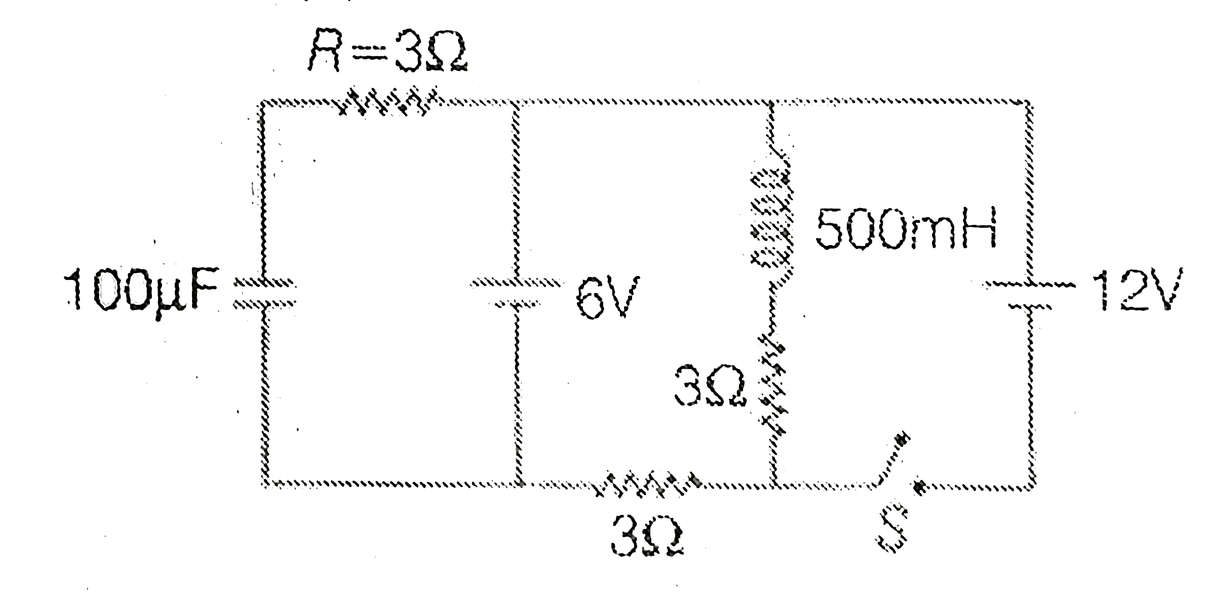
View SolutionIn the circuit diagram shown in figure, initially switch S is opened and the circuit is in steady state. At time t=0, the switch S is closed and the new steady state is reached after some time. Choose the correct option(s)
View SolutionThe circuit is in a steady state.
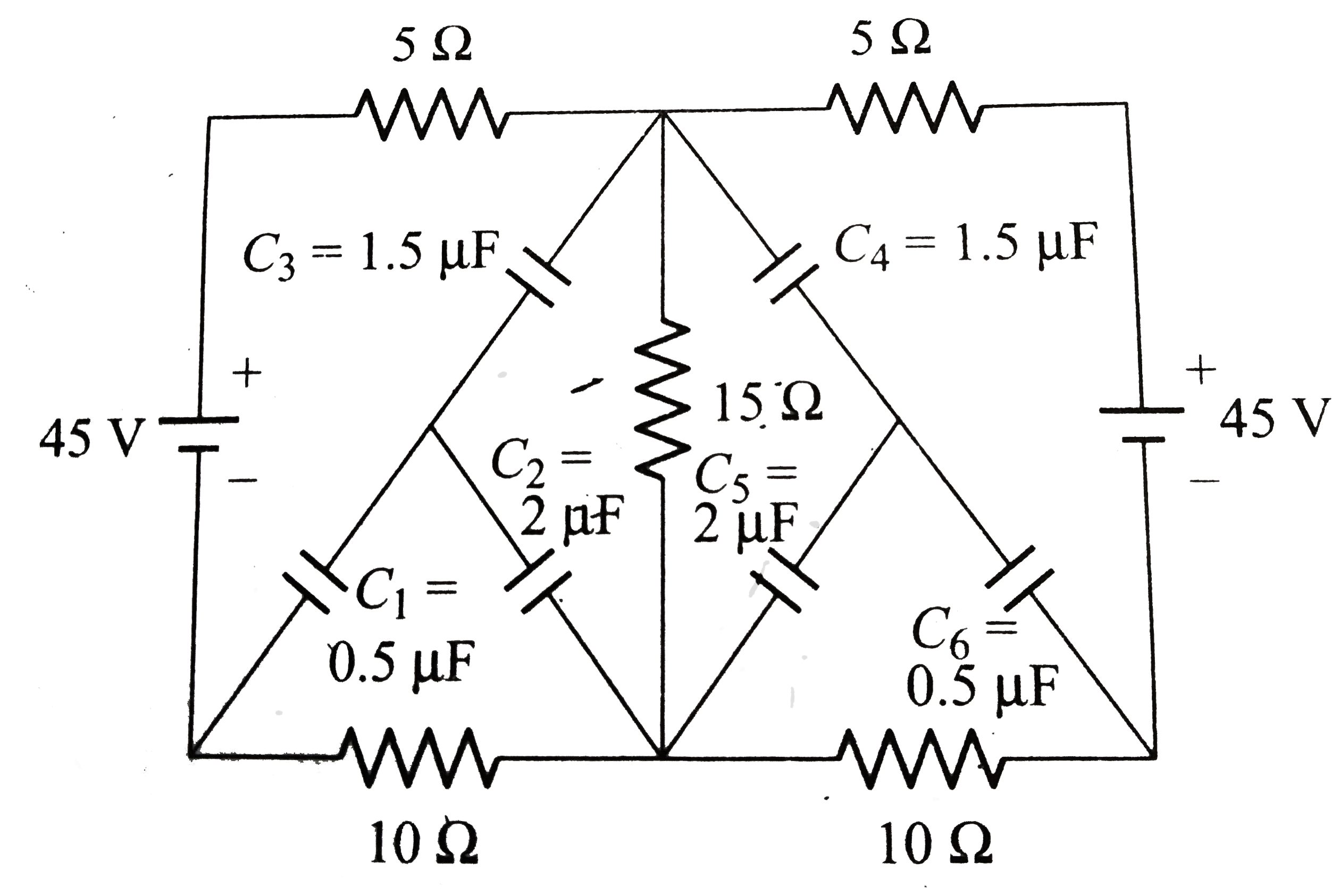
The charge in capacitor C1 is
View SolutionThe circuit is in a steady state.
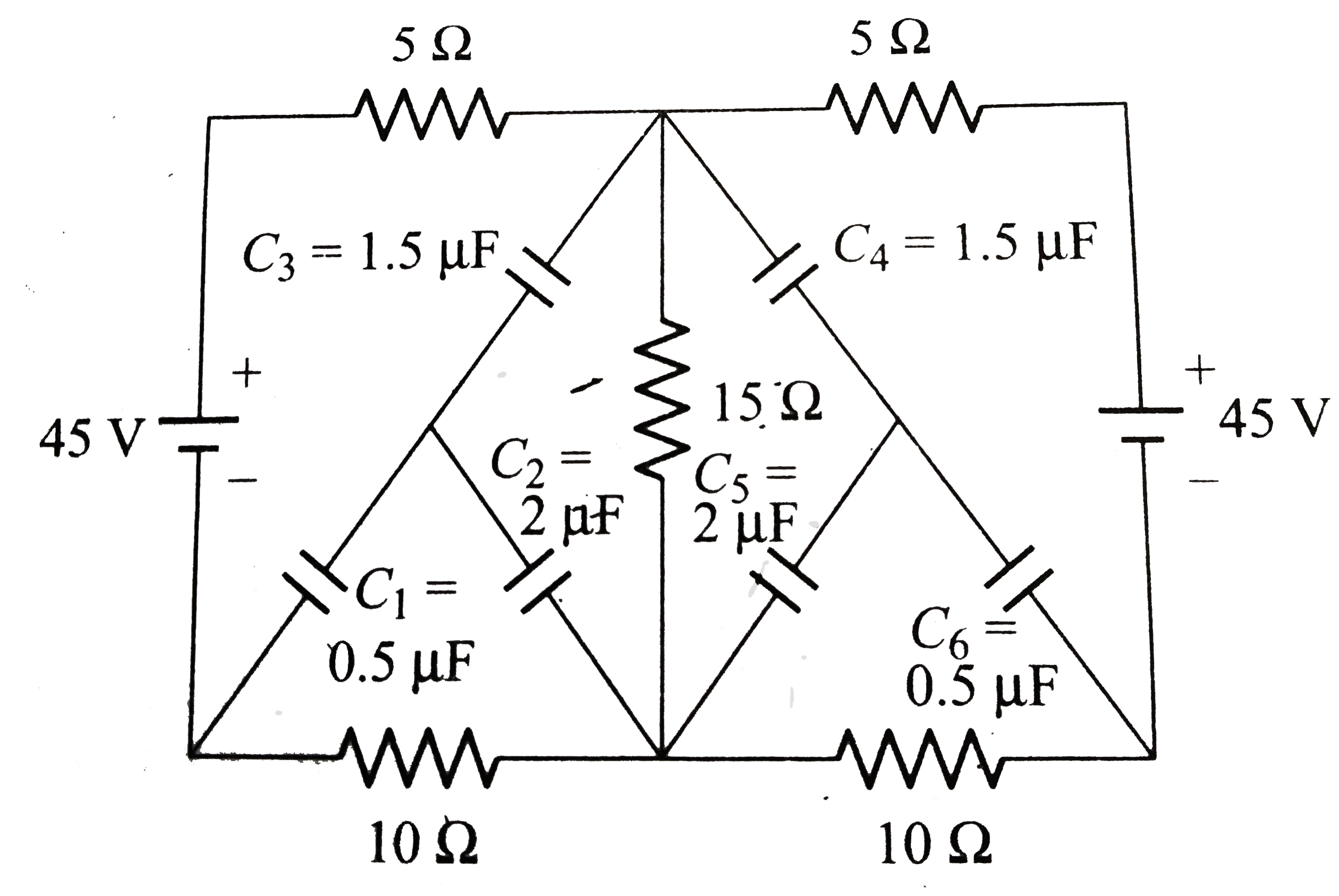
The charge in capacitor C2 is
View SolutionThe circuit is in a steady state.
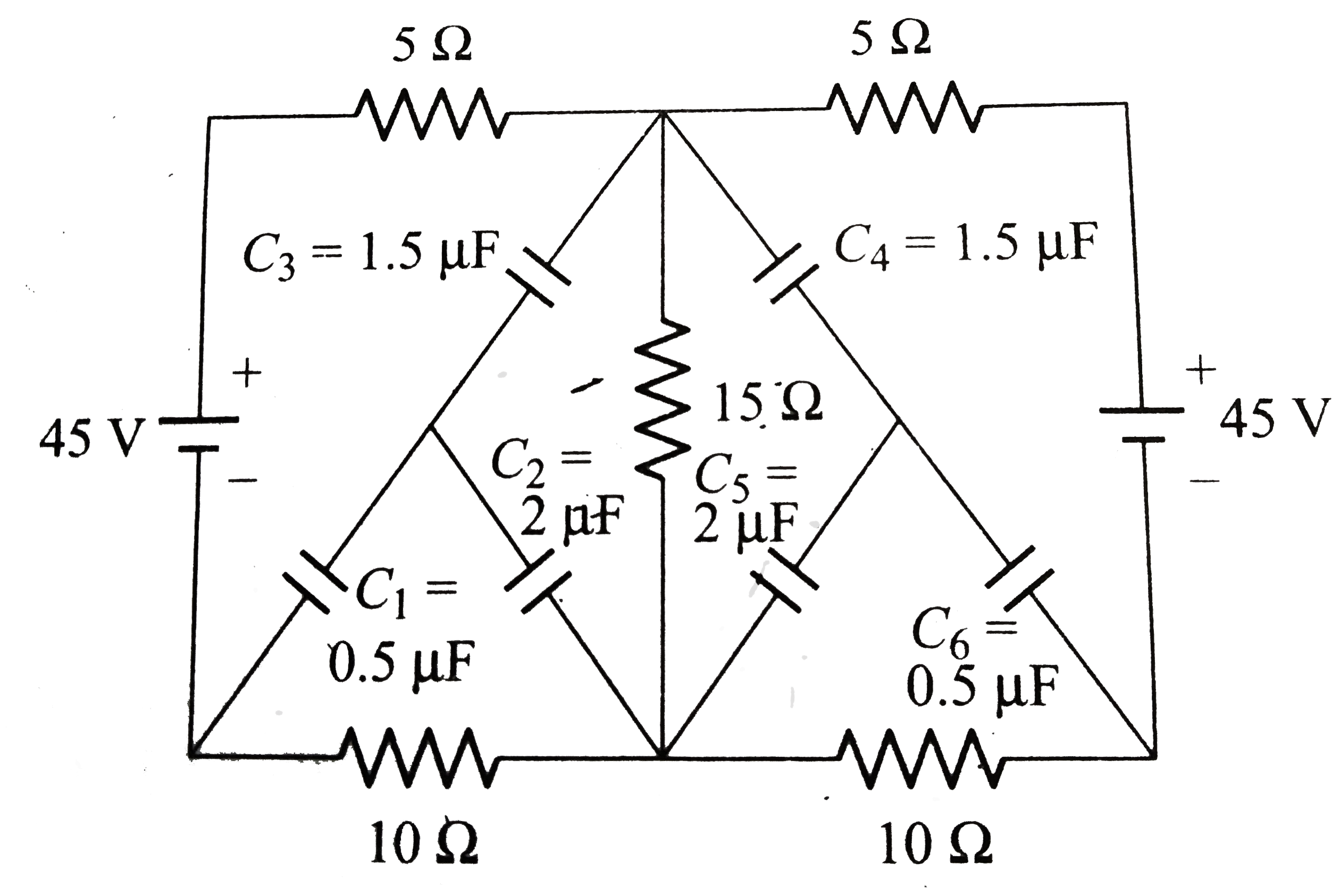
The charge in capacitor C3 is
View SolutionThe circuit consists of two resistors (of resistance R1=20Ω and R2=10Ω), a capacitor (of capacitance C=10μF) and two ideal cells. In the circuit shown the capacitor is in steady state and the switch S is open
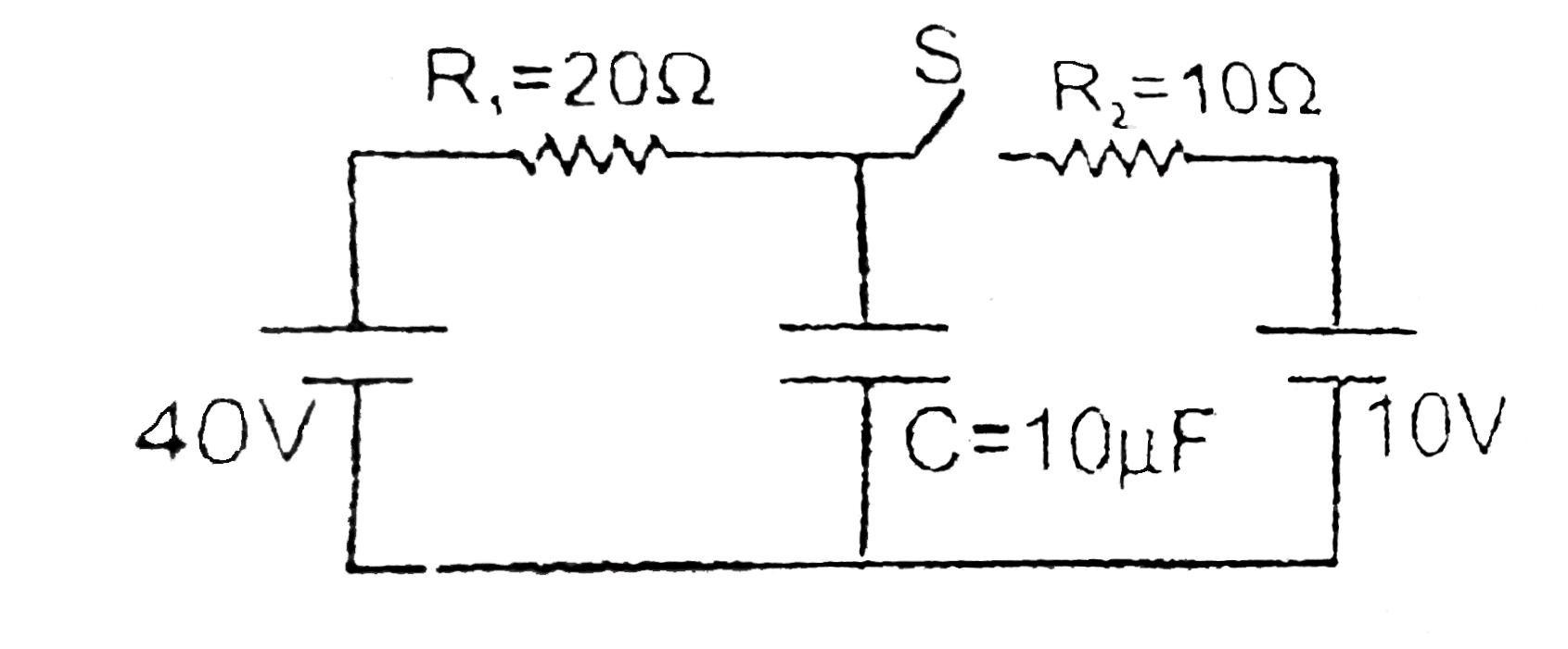
The charge on capacitor in steady state with switch S closed.
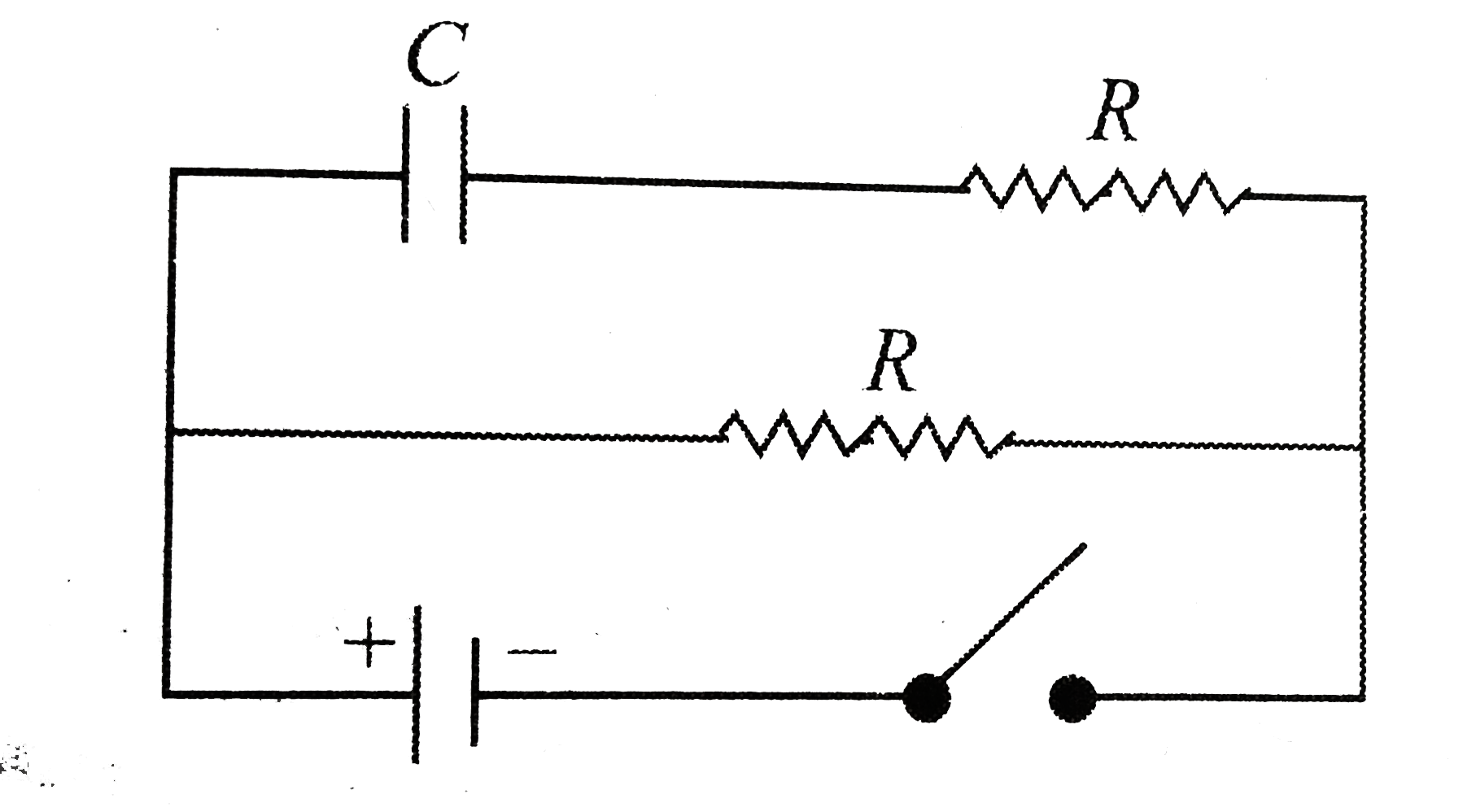
View SolutionIn the circuit shown in fig. when the switch is closed, the capacitor charges with a time constant
View SolutionThe circuit consists of two resistors (of resistance R1=20Ω and R2=10Ω), a capacitor (of capacitance C=10μF) and two ideal cells. In the circuit shown the capacitor is in steady state and the switch S is open
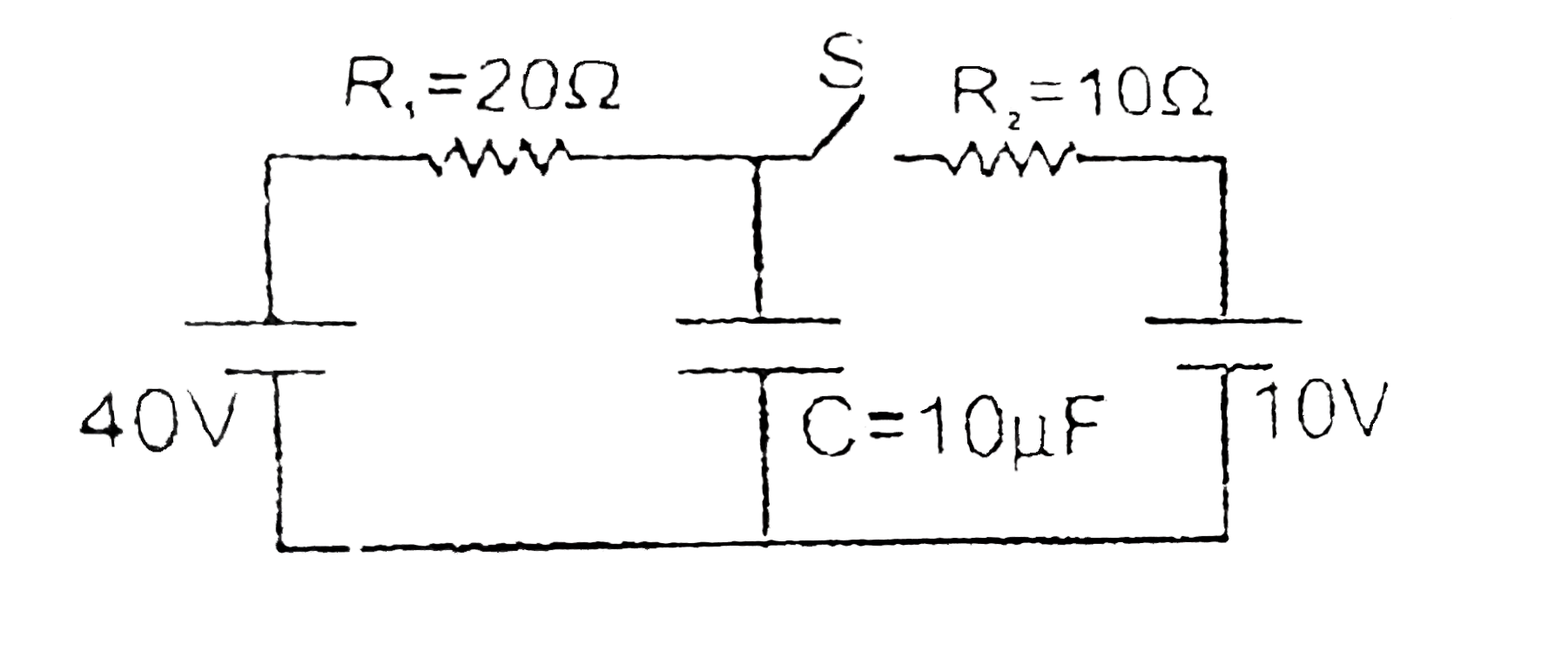
the circuit is in steady state with switch S closed. Now the switch S is opened. Just after the switch S is opened. the current through resistance R1 is
View SolutionInitially capacitor is uncharged at t=0 switch is closed. Charge on capacitor when current in the circuit is 10% of maximum current :
View SolutionIn the circuit shown in figure the switch S is closed at t = 0. A long time after closing the switch
View Solution
