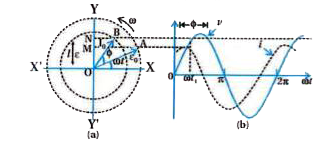
Draw phasor diagram for XC>XL and XC<XL and give the disadvantages of this method. Solution in Gujrati
If XC>XL ϕ is positive and the circuit becomes capacitive, consequently the current in the circuit leads the source voltage.
If XC<XL ϕ is negative and the circuit becomes inductive consequently the current in the circuit lags the source voltage.
The phasor diagram and variation of V and I with ωt for the case XC>XL is shown in figure.

Thus, we have obtained amplitude and phase of current for an LCR series circuit using the technique of phasors, but in this method there are certain disadvantes.
First, the phasor diagram say nothing about the initial condition.
Second, one can take any arbitrary value of t and draw different phasors. The solution so obtained is called the steady-state solution. This is not a general solution.
Moreover, we do have a transient solution which exists even for V =0.
The general solution is the sum of the transient solution and the steady -state solution.
After a sufficiently long time, the effects of the transient solution die out and the behaviour of the circuit is described by the steady -state solution.
Topper's Solved these Questions
- ALTERNATING CURRENTS BOOK - KUMAR PRAKASHANCHAPTER - ALTERNATING CURRENTS EXERCISE - SECTION B NUMERICALS (TEXTUAL ILLUSTRATIONS)
33 Videos
- ALTERNATING CURRENTS BOOK - KUMAR PRAKASHANCHAPTER - ALTERNATING CURRENTS EXERCISE - SECTION B NUMERICALS ( TEXTUAL EXERCISE )
13 Videos
- ALTERNATING CURRENTS BOOK - KUMAR PRAKASHANCHAPTER - ALTERNATING CURRENTS EXERCISE - SECTION-D MCQs (COMPETITIVE EXAMS)
64 Videos
- ATOMSBOOK - KUMAR PRAKASHANCHAPTER - ATOMSEXERCISE - Section-D -MCQs asked in GUJCET / Board Exam
34 Videos
Similar Questions
A light bulb is rated at 100W for a 220 V supply. Find the resistance of the bulb
View SolutionA 100 Ω resistor is connected to a 200V, 50 Hz ac supply.
(a) What is the rms value of current in the circuit ?
(b) What is the net power consumed over a fully cycle ?
View SolutionPower factor of AC series circuit having resistance R and inductor L having angular frequency ω is ……..
View SolutionThe ratio of longest wavelength and the shortest wavelength observed in the 5 spectral series of emission spectrum of hydrogen is .......
View SolutionIf omega is angular frequency of a.c., then the reactance offered by inductance L and capacitance C are X_(L) ……………………..and X_(C ) ……………
View SolutionThe resonance point in XL−f and XC−f curves is

View SolutionAssertion: At resonance, power factor of L-C-R series circuit is 1.
Reason: At resonance, XC=XL
View SolutionIf the median of the data , x1,x2,x3,x4,x5,x6,x7,x8 is a , then find the median of the data is x3,x4,x5,x6. (where x1<x2<x3<x4<x5<x6<x7<x8)
View SolutionIf the median of the data x1,x2,x3,x4,x5,x6,x7,x8 is αandx1<x2<x3<x4<x5<x6<x7<x8, then the median of x3,x4,x5,x6 is
View SolutionIn a series L-C-R circuit X_(L)350 Omega, X_(C)=200 Omega and R = 150 Omega .
View SolutionIn LCR circuit when X_(L)=X_(C) (at resonance) the current ……… .
View SolutionIn a certain series LCR circuit connected to an AC source XL>XC then
View SolutionIn an L-C-R series circuit R = 10Omega, X_(L) = 8Omega and X_(C) = 6Omega the total impedance of the circuit is -
View SolutionIf XC>XL the current in the circuit is ahead or behind of the voltage ?
View SolutionIf XC<XL the current in the circuit is ahead or behind of the voltage ?
View Solution
