Obtain the relation of voltage applied to a series LCR circuit. Solution in Gujrati
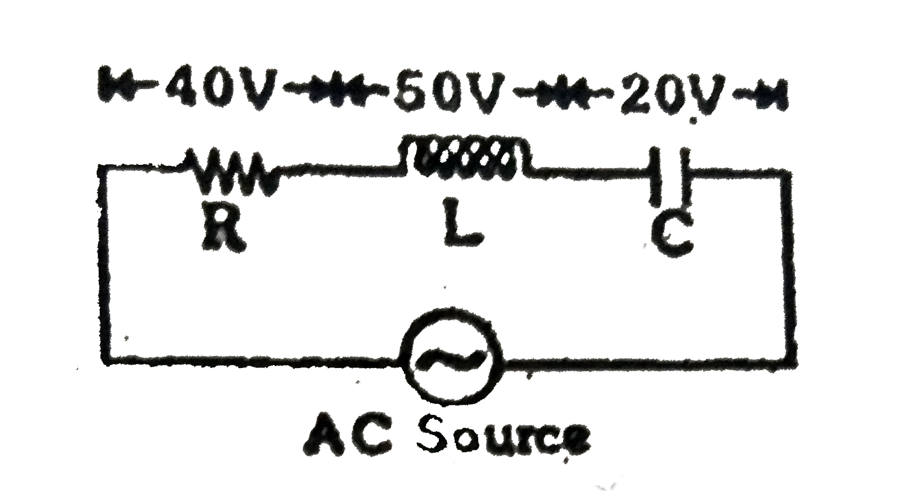
Below figure shows a series LCR circuyit connected to an AC source .ε.. Voltage of an AC source is V=Vmsinωt.

Let q is the charge on the capacitor and I the current at time t,
∴V=VL+VR+VC
From Kirchhoff.s loop rule LdIdt+IR+qC=V
From Kirchhoff.s loop rule LdIdt+IR+qC=V where potential difference across the ends =LdIdt
potential difference across the ends of capacitor =qC and potential difference across the ends of resistance =IR.
Topper's Solved these Questions
- ALTERNATING CURRENTS BOOK - KUMAR PRAKASHANCHAPTER - ALTERNATING CURRENTS EXERCISE - SECTION B NUMERICALS (TEXTUAL ILLUSTRATIONS)
33 Videos
- ALTERNATING CURRENTS BOOK - KUMAR PRAKASHANCHAPTER - ALTERNATING CURRENTS EXERCISE - SECTION B NUMERICALS ( TEXTUAL EXERCISE )
13 Videos
- ALTERNATING CURRENTS BOOK - KUMAR PRAKASHANCHAPTER - ALTERNATING CURRENTS EXERCISE - SECTION-D MCQs (COMPETITIVE EXAMS)
64 Videos
- ATOMSBOOK - KUMAR PRAKASHANCHAPTER - ATOMSEXERCISE - Section-D -MCQs asked in GUJCET / Board Exam
34 Videos
Similar Questions
A light bulb is rated at 100W for a 220 V supply. Find the resistance of the bulb
View SolutionA 100 Ω resistor is connected to a 200V, 50 Hz ac supply.
(a) What is the rms value of current in the circuit ?
(b) What is the net power consumed over a fully cycle ?
View SolutionPower factor of AC series circuit having resistance R and inductor L having angular frequency ω is ……..
View SolutionThe ratio of longest wavelength and the shortest wavelength observed in the 5 spectral series of emission spectrum of hydrogen is .......
View SolutionIn a series LCR circuit, voltage drop axross L can be more than applied voltage (True/false).
View SolutionSTATEMENT-1: In a series LCR circuit at resonance, the voltage across the capacitor or inductor may be more than the applied voltage.
STATEMENT-2: At resonance in a series LCR circuit, the voltages across inductor and capacitor are out of phase.
View SolutionIn an LCR series circuit the voltages across R,L and C at resonance are 40Vand60V respectively the applied voltage is .
View SolutionIn series LCR circuit, the voltages across R, L and C are shown in the figure. The voltage of applied source

View SolutionIn a series LCR circuit, the voltage across the inductance and capacitance are not
View SolutionIn a LCR series circuit, if the phase difference between applied voltage and current is zero then
View SolutionWhen the frequency of the ac voltage applied to a series LCR circuit is gradually increased from a low value , the impedance of the circuit.
View SolutionDerive an expression for the impedance of a series LCR, circuit, when an AC voltage is applied to it.
View SolutionAlternating Current | AC Voltage Applied To A Series LCR Circuit
View SolutionDerive an expression for the impedance of a series LCR, circuit, when an AC voltage is applied to it.
View SolutionObtain the relation of phase between instantaneous current and voltage with the help of phase diagram for series LCR circuit.
View Solution
