An ideal cell of emf 10 V is connected in circuit shown in figure. Each resistance is 2Ω . The potential difference (in V) across the capacitor when it is fully charged is _______.
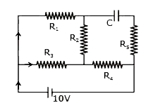
The correct Answer is:8
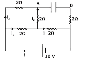
I=1043+2=10×310=3 Amp
i1=2 Amp
i2=1 Amp
VAB=1×2+3×2=8V
Topper's Solved these Questions
Similar Questions
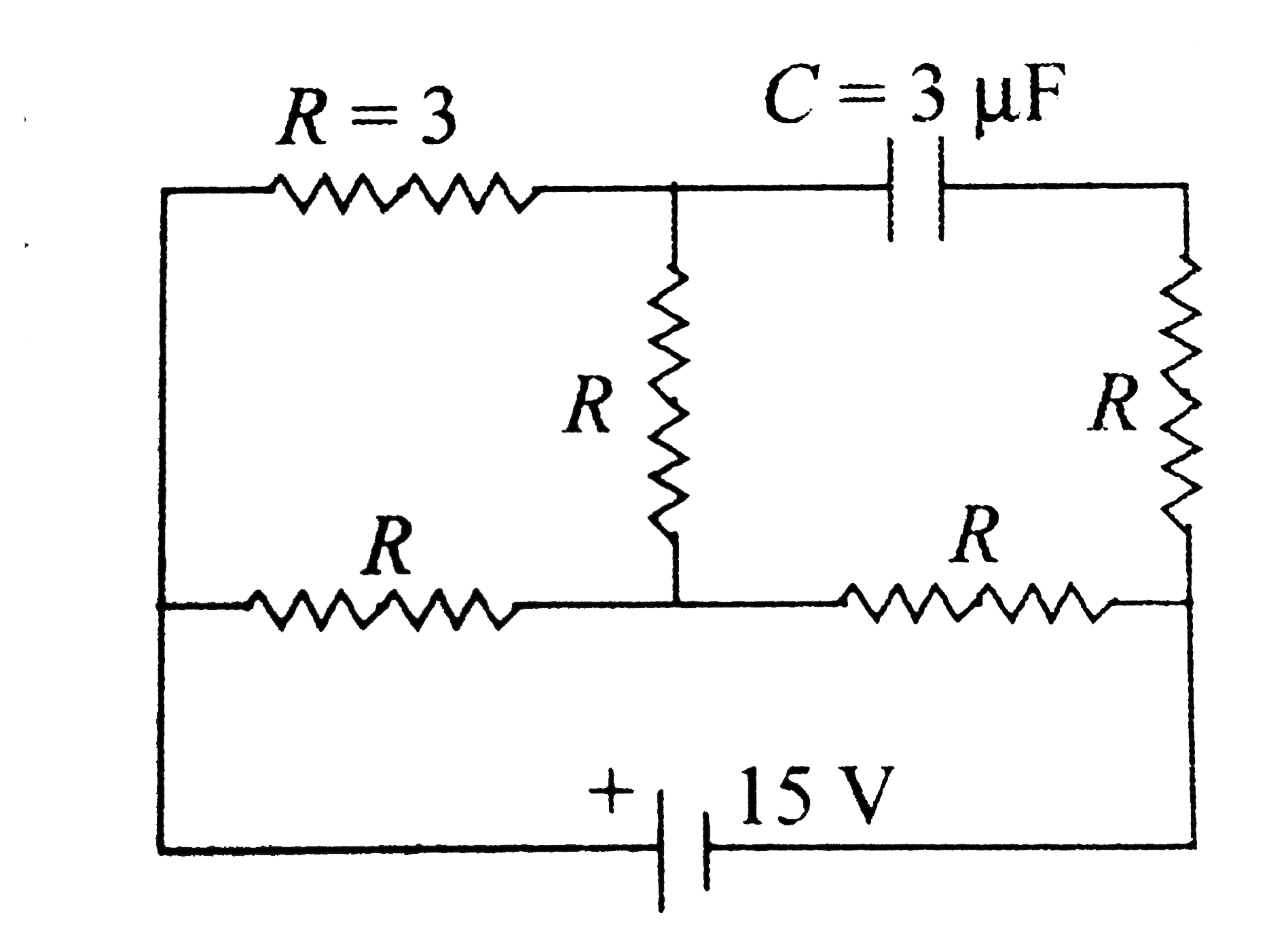
In the circuit shown in fig. the cell is ideal with emf 15V. Each resistance is of 3Ω. The potential difference across the capacitoro in steady state is
View SolutionA 220 V A supply is connected between points A and B in figure. What will be the potential difference V across the capacitor?
View Solution
Knowledge Check
A 220 V ac supply is connected between points A and B as shown 220 V in figure. What will be the potential AC difference V across the capacitor?
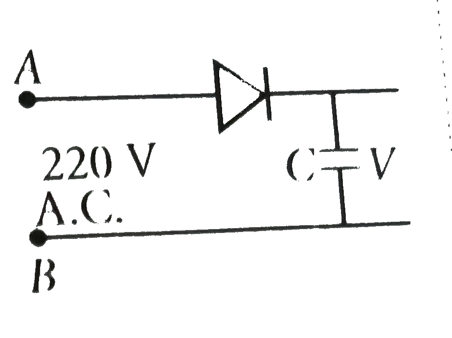 A220 VB110 VC0 VD200√2V
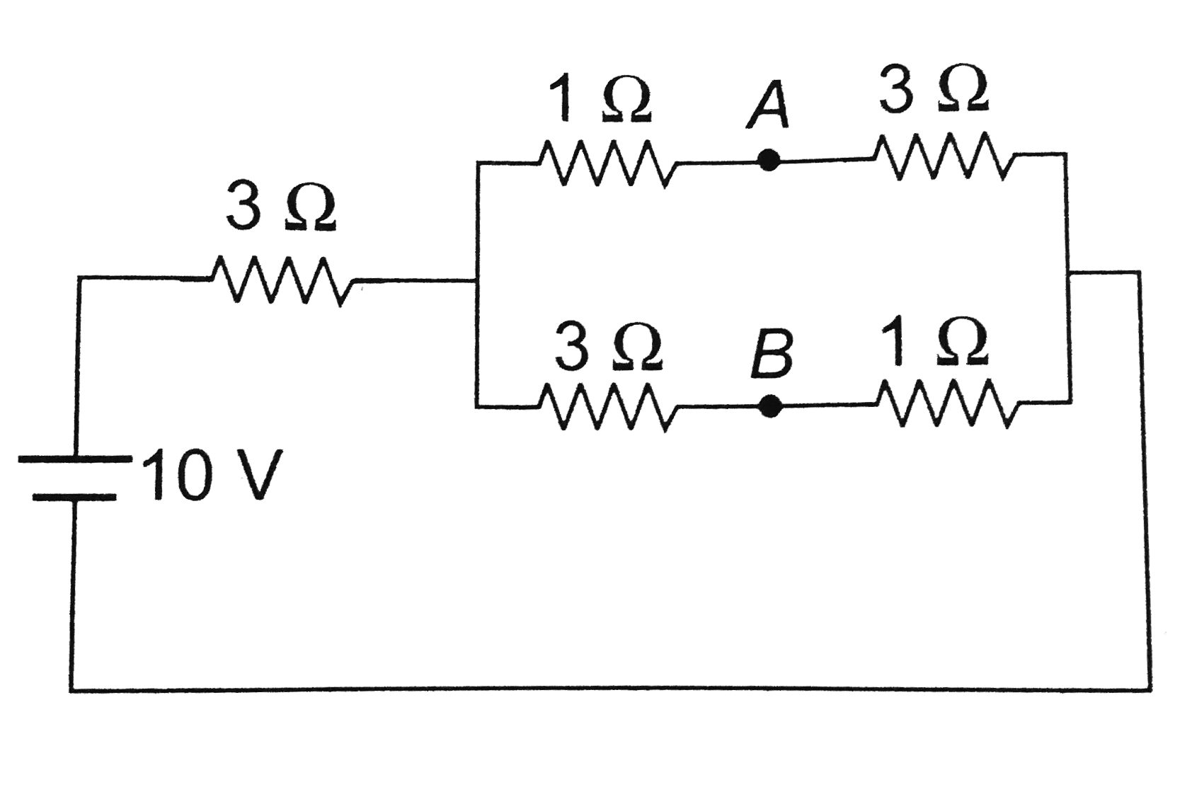
A battery of e.m.f. 10V is connected to resistance as shown in figure. The potential difference VA−VB between the point A and B is
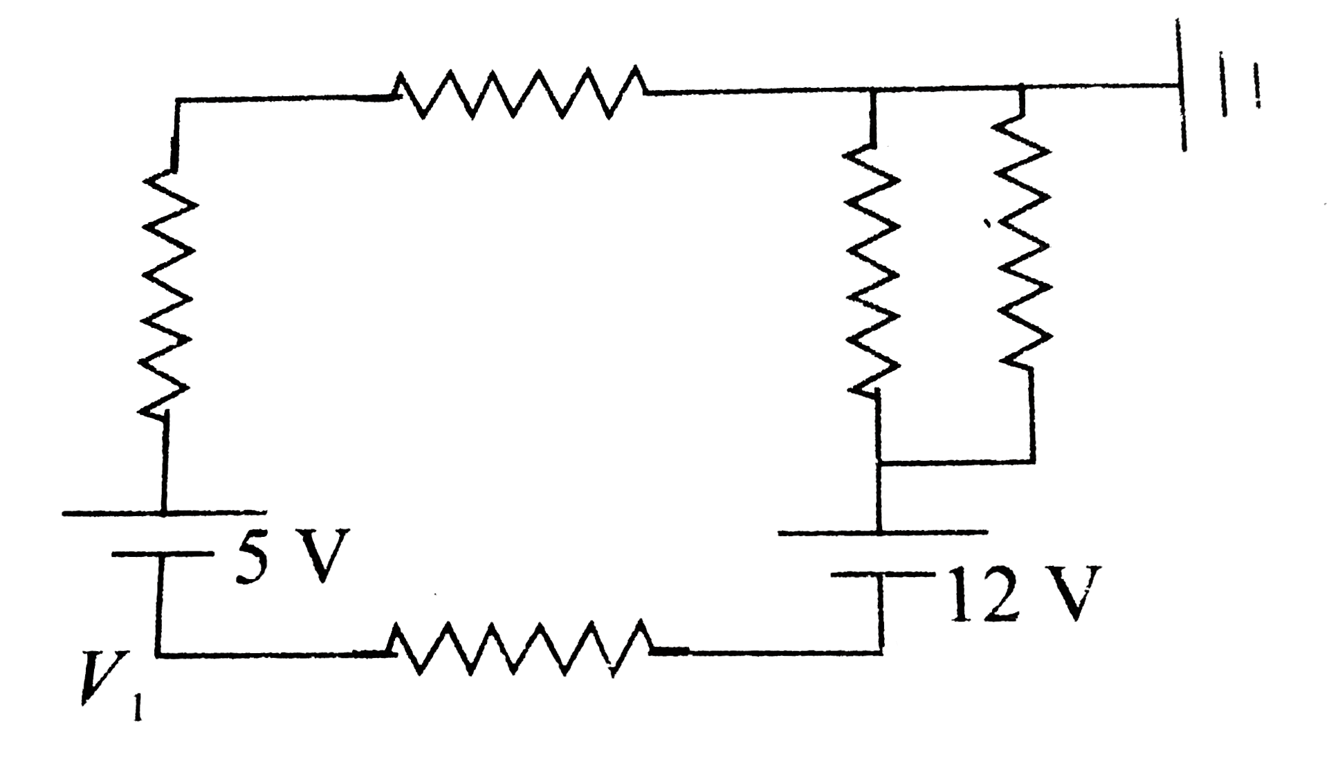
View SolutionIn the circuit shown, each resistance is 2Ω. The potential V1 is an indicated in the circuit. What is the magnitude of V1 in volt ?
View SolutionA cell which has an emf 1.5 V is connectedin series with an external resistance of 10Ω. If the potential difference across the cell is 1.25 V, then the internal resistance of the cell is (inΩ)
View SolutionIn the circuit shown in figure

E1=10V,E2=4V,r1=r2=1Ω and R=2Ω.
Find the potential difference across battery 1 and battery 2.
View SolutionIn the circuit shown in figure

E1=10V,E2=4V,r1=r2=1Ω and R=2Ω.
Find the potential difference across battery 1 and battery 2.
View SolutionA capacitor of capacitance 1μF is connected in parallel with a resistance 10Ω and the combination is connected across the terminals of a battery of EMF 50 V and internal resistance 1Ω. The potential difference across the capacitor at steady state is (in Volt)
View SolutionA cell of emf E is connected across a resistance R. The potential difference between the terminals of the cell is found to be V. The internal resistance of the cell must be -
View Solution
