Give any four precautions taken by a student to perform an experiment to determine the resultant resistance of two resistors when connected in series.
To determine the resultant resistance of two resistors connected in series, a student should take the following four precautions:
1. Ensure a Closed Circuit:
- Before starting the experiment, the student must check that all connections are properly made and that the circuit is closed. This ensures that current can flow through the circuit without any interruptions.
2. Proper Connection of Meters:
- The student should ensure that the ammeter is connected in series with the resistors and the voltmeter is connected in parallel across the resistor whose voltage drop is being measured. This is crucial for obtaining accurate readings.
3. Tight Connections:
- All connections in the circuit should be tight. Loose connections can lead to fluctuations in current and voltage readings, which can introduce errors in the measurement of resistance.
4. Close the Key Only When Taking Readings:
- The student should only close the circuit key when taking readings. Keeping the key closed for extended periods can cause the resistors to heat up, leading to changes in resistance and inaccurate results.
- Before starting the experiment, the student must check that all connections are properly made and that the circuit is closed. This ensures that current can flow through the circuit without any interruptions.
- The student should ensure that the ammeter is connected in series with the resistors and the voltmeter is connected in parallel across the resistor whose voltage drop is being measured. This is crucial for obtaining accurate readings.
- All connections in the circuit should be tight. Loose connections can lead to fluctuations in current and voltage readings, which can introduce errors in the measurement of resistance.
- The student should only close the circuit key when taking readings. Keeping the key closed for extended periods can cause the resistors to heat up, leading to changes in resistance and inaccurate results.
Similar Questions
List any five precautions to be taken while performing an experiment in a chemistry laboratory.
View SolutionConsider a box with three terminals on top of it as shown in figure.
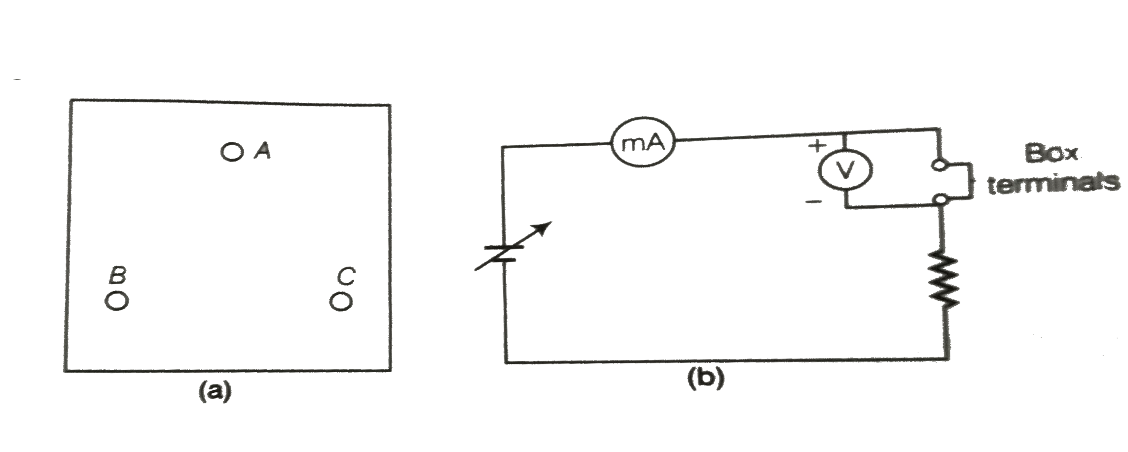
Three components namely, two germanium diodes and one resistor are connected across these three terminals in some arrangement
A student performs an experiment in which any two of these three terminals are connected in the circuit shown in figure.
The student obtains graphs of current-voltage characteristics for unknown combination of components between the two terminals connected in the circuit. The graphs are
(i) When A is positive and B is negative
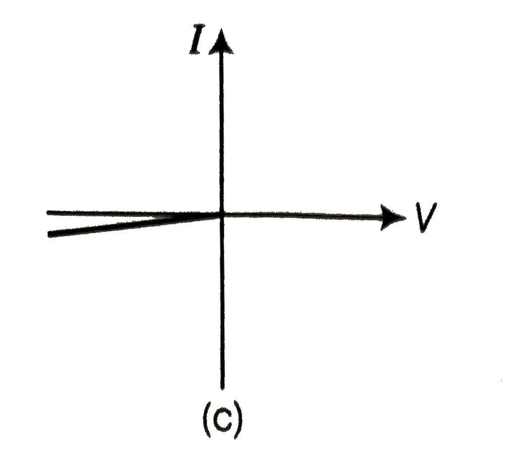
(ii) When A is negative and B is positive
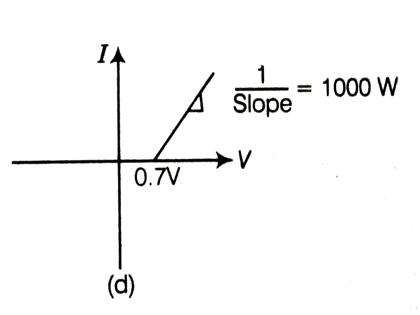
(iii) When B is negative and C is positve
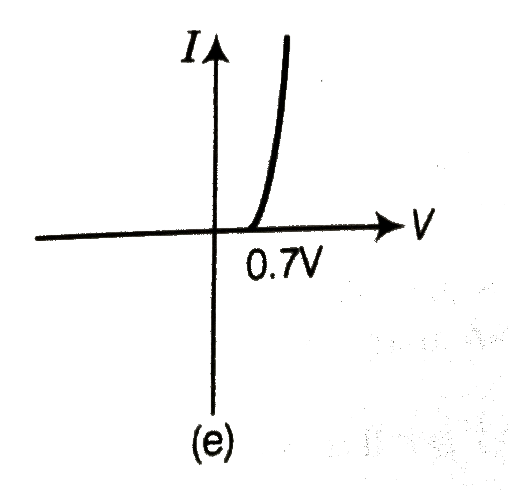
(iv) When B is positive and C is neagtive
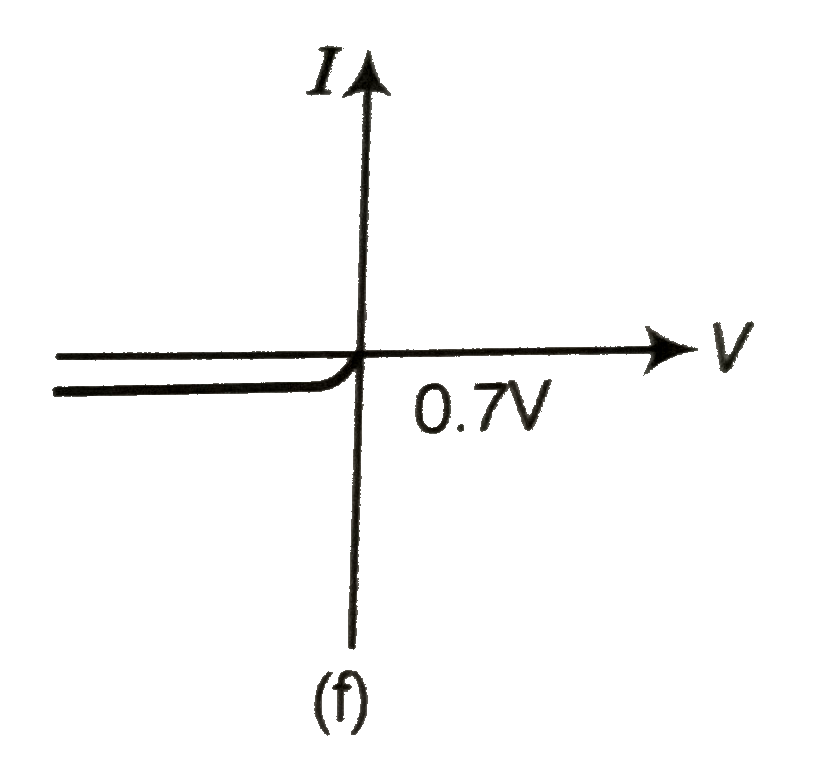
(v) When A is positive and C is negative
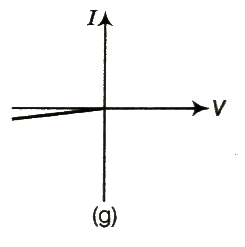
(vi) When A is negative and C is positive
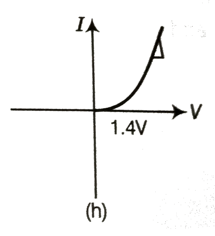
From these graphs of current − voltage characteristic shown in fig. (c) to (h) determine the arrangement of components between A, B and C.
View SolutionTwo equal resistors are connected in series. Draw the circuit diagram for determining the resultant resistance.
View SolutionA set of n identical resistors, each of resistance RΩ, when connected in series have an effective resistance XΩ and when the resistors are connected in parallel, their effective resistance is YΩ. Find the relation between R, X and Y.
View SolutionResistance n, each of rohm, when connected in parallel give an equivalent resistance of Rohm. If these resistances were connected series, the combination would have a resistance in ohm, equal to
View SolutionTwo resistors with temperature coefficients of resistance α1 and α2 have resistances R01 and R02 at 0∘C. Find the temperature coefficient of the compound resistor consisting of the two resistors connected.
a.. In series and
b. in paralllel
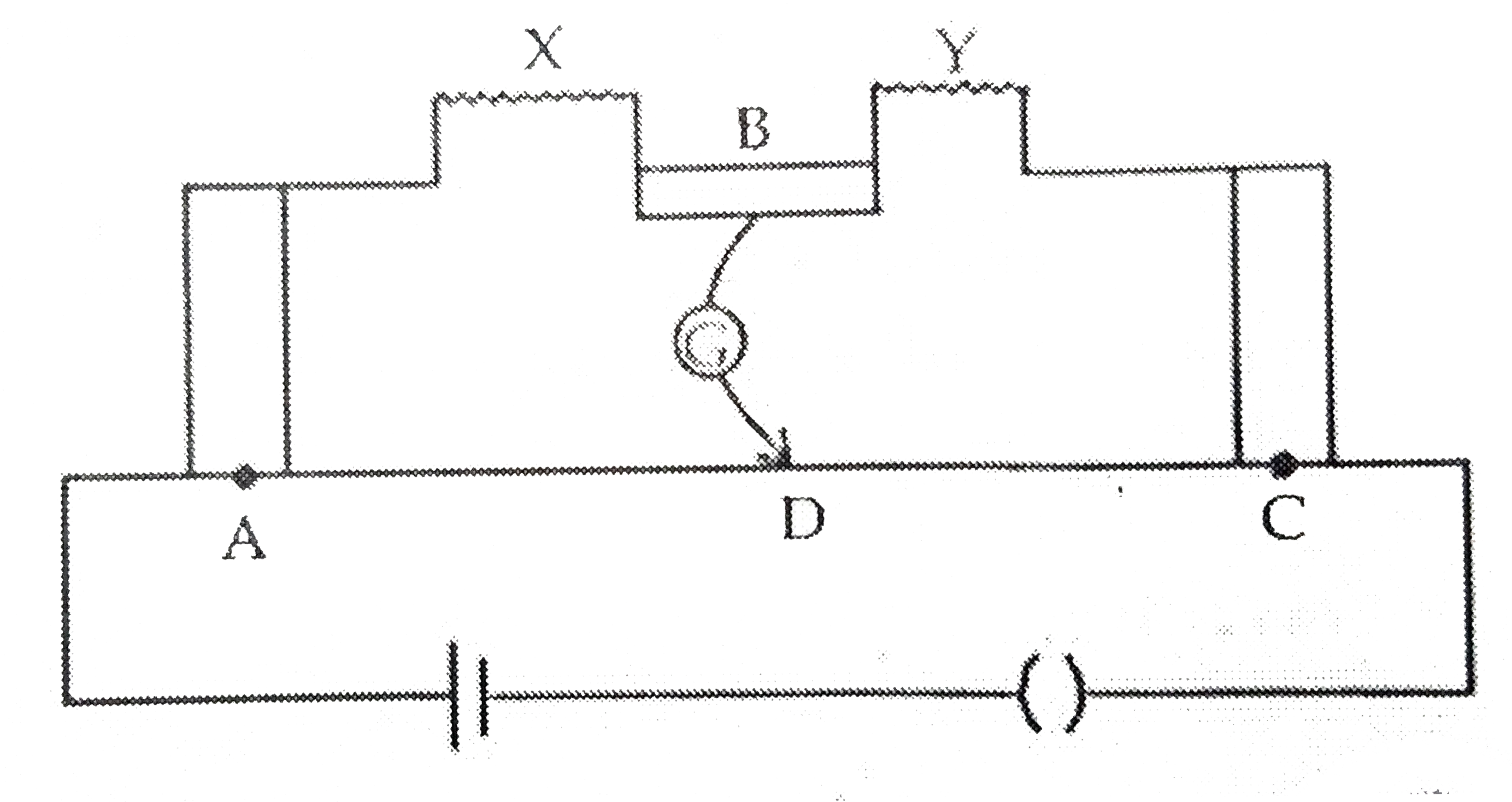
View SolutionThe figure shows experimental set up of a meter bridge. When the two unknown resistances X and Y are inserted, the null point D is obtained 40 cm from the end A. When a resistance of 10Ω is connected in series with X, the null point shifts by 10 cm. Find the position of the null point when the 10Ω resistance is instead connected in series with resistance 'Y'. Determine the value of the resistance X and Y
View SolutionThere are n similar conductors each of resistance R . The resultant resistance comes out to be x when connected in parallel. If they are connected in series, the resistance comes out to be
View SolutionLet there be n resistors R1...Rn with Rmax=max(R1....Rn) and Rmin=min{R1...Rn}. Show that when they are connected in parallel the resultant resistance Rp=Rmin and when they are connected in series, the resultant resistance RS>Rmax. Interpret the result physically.
View SolutionTwo resistances are connected in the two gaps of a meter bridge. The balance point is 20cm from the zero end. When a resistance 15Ω is connected in series with the smaller of two resistance, the null point+ shifts to 40cm. The smaller of the two resistance has the value.
View Solution
