Four student have made the following circuit diagrams for determining the equivalent resistance of two resistors connected in series :
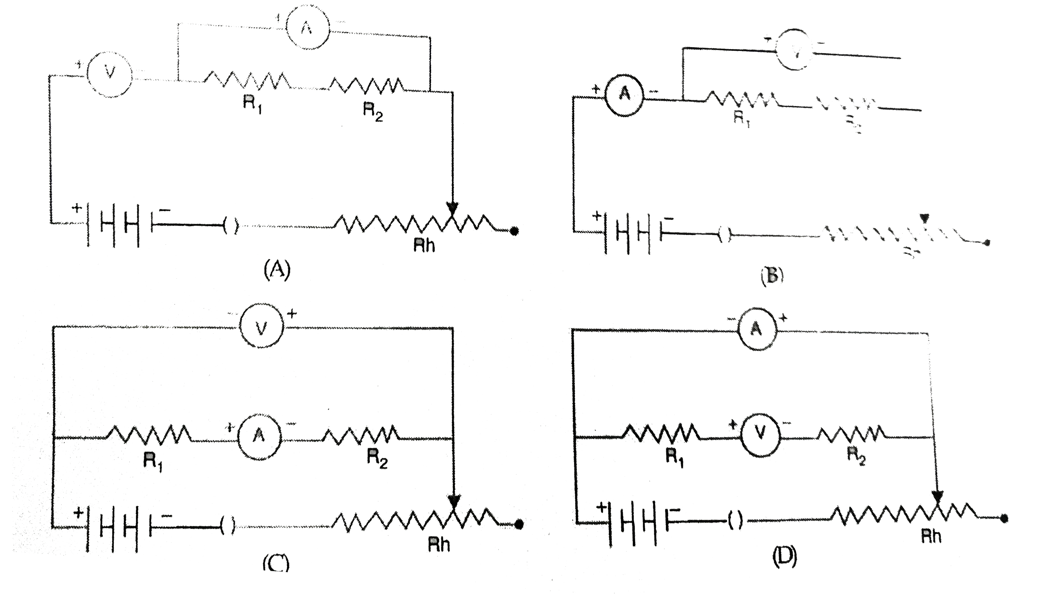
The correct circuit diagram is :
A
B
C
D
The correct Answer is:B
NA
Topper's Solved these Questions
- THE HUMAN EYE AND THE COLOURFUL WORLD BOOK - LAKHMIR SINGH & MANJIT KAURCHAPTER - THE HUMAN EYE AND THE COLOURFUL WORLD EXERCISE - Long Answer Type Question
3 Videos
- THE HUMAN EYE AND THE COLOURFUL WORLD BOOK - LAKHMIR SINGH & MANJIT KAURCHAPTER - THE HUMAN EYE AND THE COLOURFUL WORLD EXERCISE - NCERT Book
14 Videos
- THE HUMAN EYE AND THE COLOURFUL WORLD BOOK - LAKHMIR SINGH & MANJIT KAURCHAPTER - THE HUMAN EYE AND THE COLOURFUL WORLD EXERCISE - Long Answer Type Questions
2 Videos
- TEST PAPER 4BOOK - LAKHMIR SINGH & MANJIT KAURCHAPTER - TEST PAPER 4EXERCISE - SECTION A
10 Videos
Similar Questions
(a) With the help of a circuit diagram, obtain the relation for the equivalent resistance of two resistances connected in parallel.
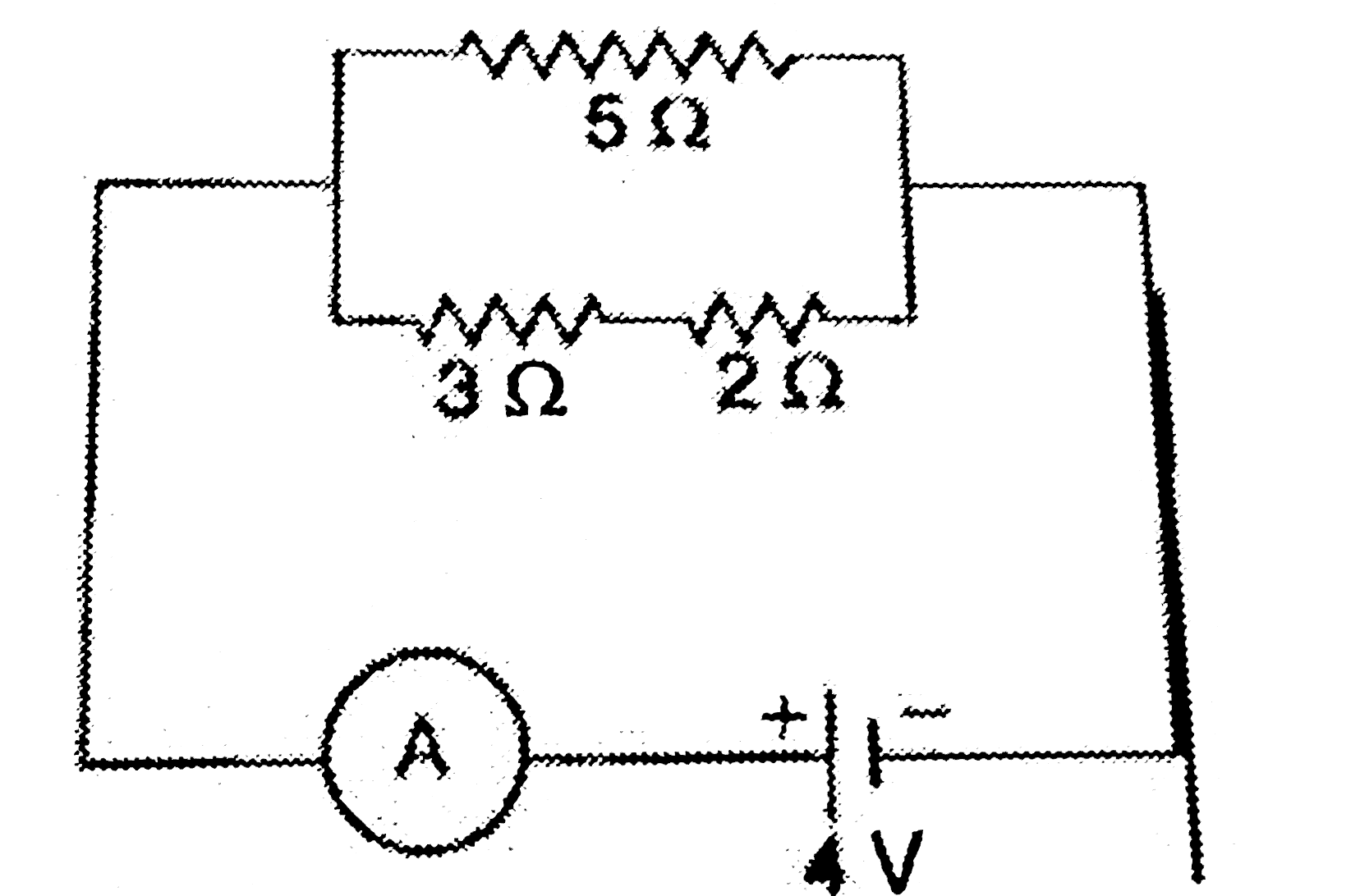
(b) In the circuit diagram shown below, find:
(i) Total resistance.
(ii) Current shown by the ammeter A
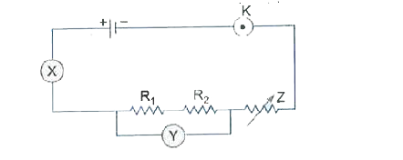
View SolutionThe given circuit diagram shows the experimental arrangement of different circuit components for determination of equivalent resistance of two resistors connected in series. Identify the components X, Y and Z shown in the circuit respectively.
View Solution
Knowledge Check
The equivalent resistance of resistors connected in series is always
AEqual to the mean of component resistorsBLess than the lowest of component resistorsCIn between the lowest and the highest of component resistorsDEqual to sum of component resistorsIn an experiment to find the equivalent resistance of two resistors connected in series, a student uses the circuit shown :
This circuit will give :
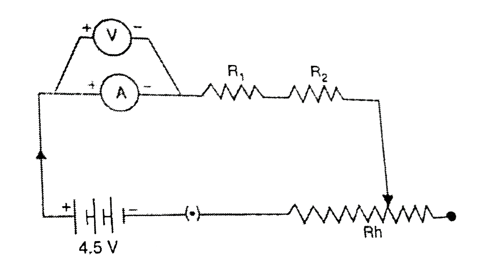 Acorrect reading for voltage V but incorrect reading for current IBcorrect reading for current I but incorrect reading for voltage (V)Ccorrect readings for both voltage V and current IDIncorrect readings for both current I and voltage V
A student stes up an electric circuit shown here for finding the equivalent resistance of two resistors in series :
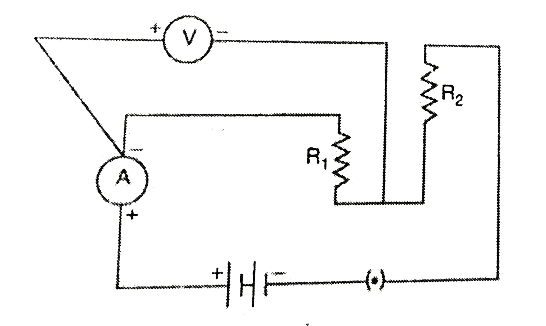
In this circuit, the :Aresistors have been connected correctly but the voltmeter has been wrongly connectedBresistors have been connected correctly but the ammeter has been wrongly connectedCresistors as well as the voltmeter have been wrongly connectedDresistors as well as the ammeter have been wrongly connected
(a) With the help of a circuit diagram, deduce the equivalent resistance of two resistances connected in series.
(b) Two resistances are connected in series as shown in the diagram:
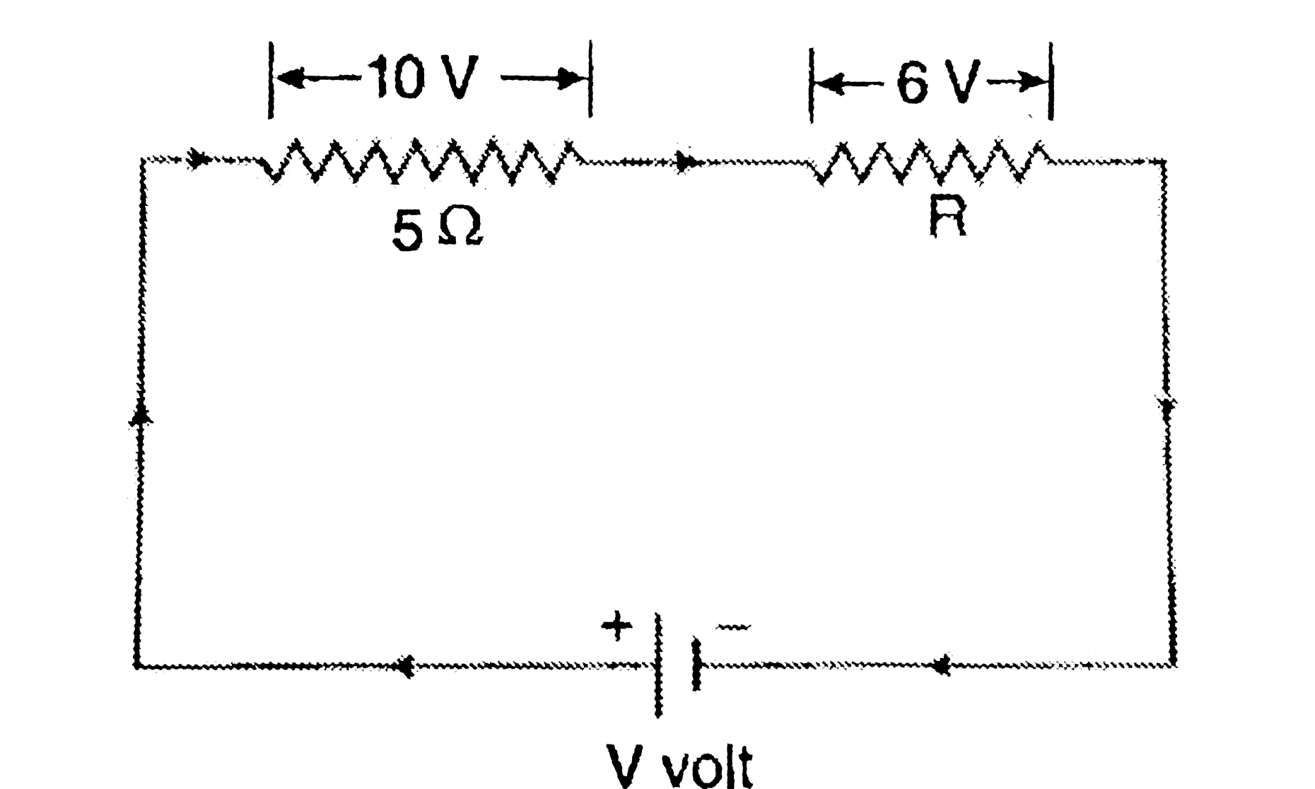
(i) What is the current through the 5 ohm resistance?
(ii) What is the current through R?
(iii) What is the value of R?
(iv) What is the value of V?
View Solution(a) With the help of a diagram, derive the formula for the resultant resistance of these resistors connected in series.
(b) For the circuit shown in the diagram given below:
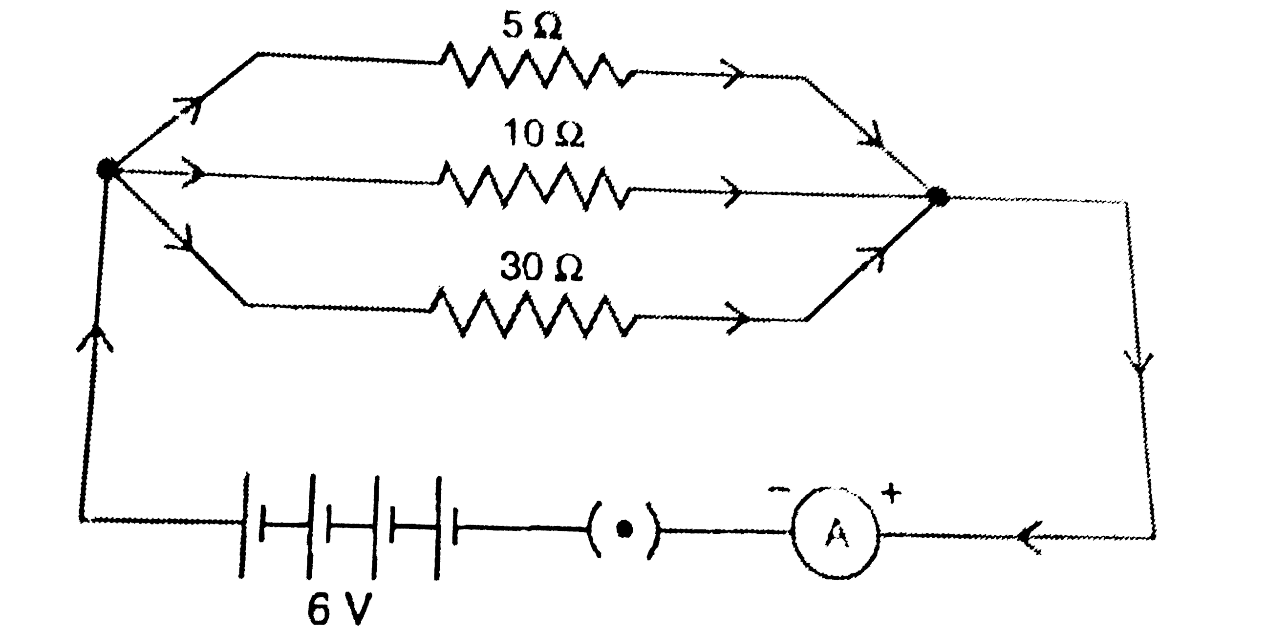
Calculate:
(i) the value of current each resistor.
(ii) the total current in the circuit.
(iii) the total effective resistance of the circuit.
View SolutionIn the following star circuit diagram (figure), the equivalent resistance between the points A and H will be
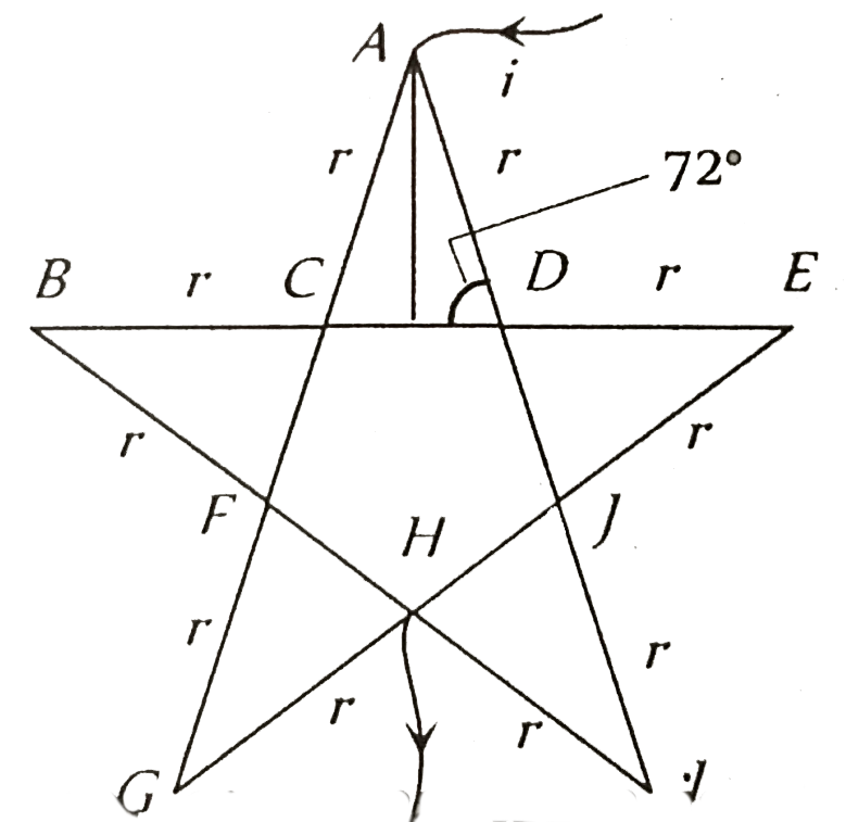
View SolutionTwo students made two circuits A and B to determine the resultant resistance of two resistors R1 and R2 connected in series :
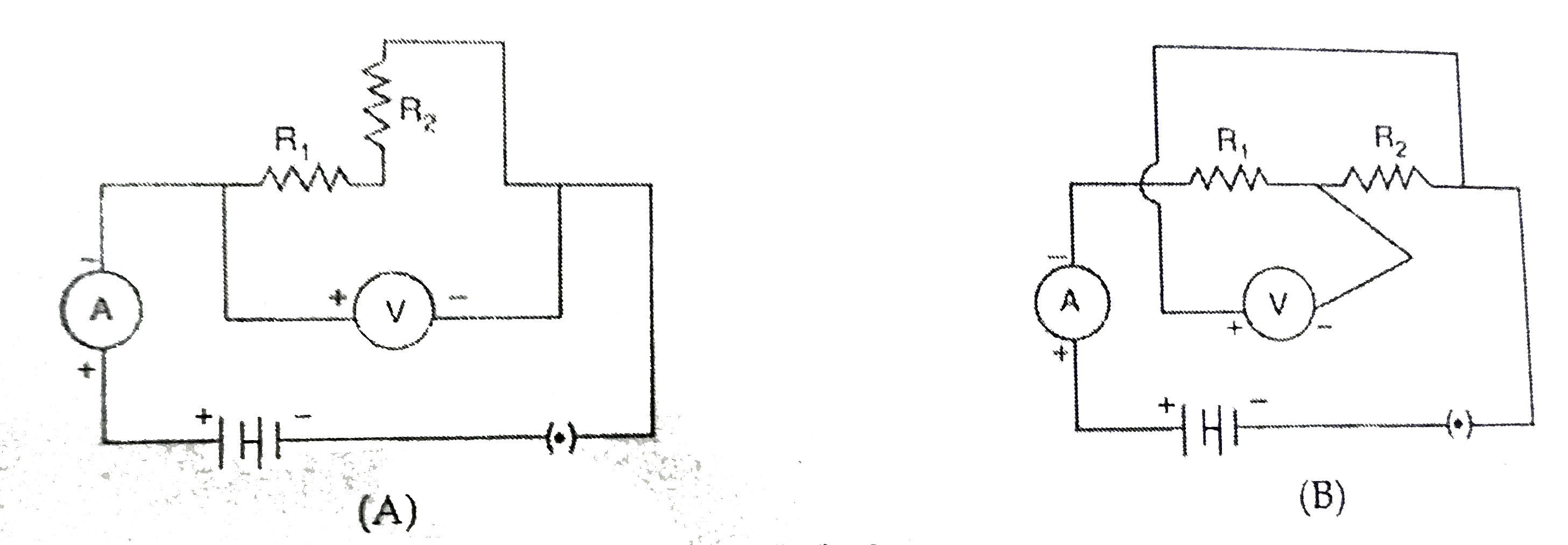
All the components have been connected correctly in :
View SolutionChoose the appropriate set of apparatus for performing the experiment to determine the equivalent resistance of two resistors when connected in series :
View Solution
