(a) With the help of a diagram, derive the formula for the resultant resistance of these resistors connected in series.
(b) For the circuit shown in the diagram given below:
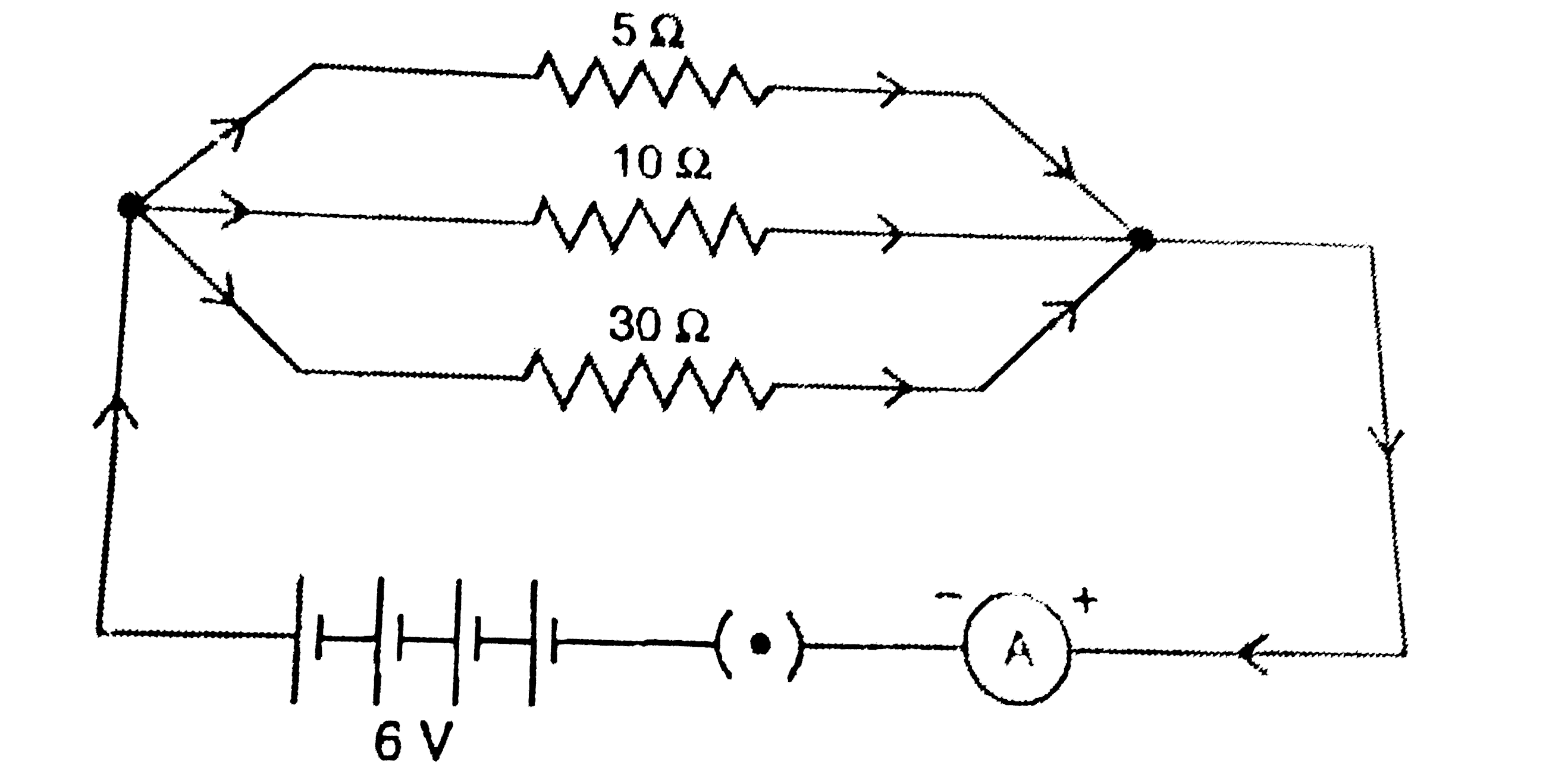
Calculate:
(i) the value of current each resistor.
(ii) the total current in the circuit.
(iii) the total effective resistance of the circuit.
The correct Answer is:(b) (i) Current through 5Ω resistor =1.2A; Current through 10Ω resistor =0.6A; Current through 30Ω resistor =0.2A (ii) 2A (iii) 3Ω
Step by step video, text & image solution for (a) With the help of a diagram, derive the formula for the resultant resistance of these resistors connected in series. (b) For the circuit shown in the diagram given below: Calculate: (i) the value of current each resistor. (ii) the total current in the circuit. (iii) the total effective resistance of the circuit. by Physics experts to help you in doubts & scoring excellent marks in Class 10 exams.
Updated on:21/07/2023Topper's Solved these Questions
- ELECTRICITY BOOK - LAKHMIR SINGH & MANJIT KAURCHAPTER - ELECTRICITY EXERCISE - Very Short Answer Type Questions
1 Videos
- ELECTRICITY BOOK - LAKHMIR SINGH & MANJIT KAURCHAPTER - ELECTRICITY EXERCISE - Short Answer Type Questions
2 Videos
- ELECTRICITY BOOK - LAKHMIR SINGH & MANJIT KAURCHAPTER - ELECTRICITY EXERCISE - Sample Problem
1 Videos
- MAGNETIC EFFECT OF ELECTRIC CURRENT BOOK - LAKHMIR SINGH & MANJIT KAURCHAPTER - MAGNETIC EFFECT OF ELECTRIC CURRENT EXERCISE - NCERT BOOK
2 Videos
Similar Questions
For the given circuit diagram calculate:

(i) the current through each resistor.
(ii) the total current in the circuit.
(iii) the total effective resistance of the circuit
View SolutionIn the circuit diagram given in (Fig. 3.57), calculate :
(a) the current through each resistor
(b) the total current in the circuit
( c) the total effective resistance of the circuit.
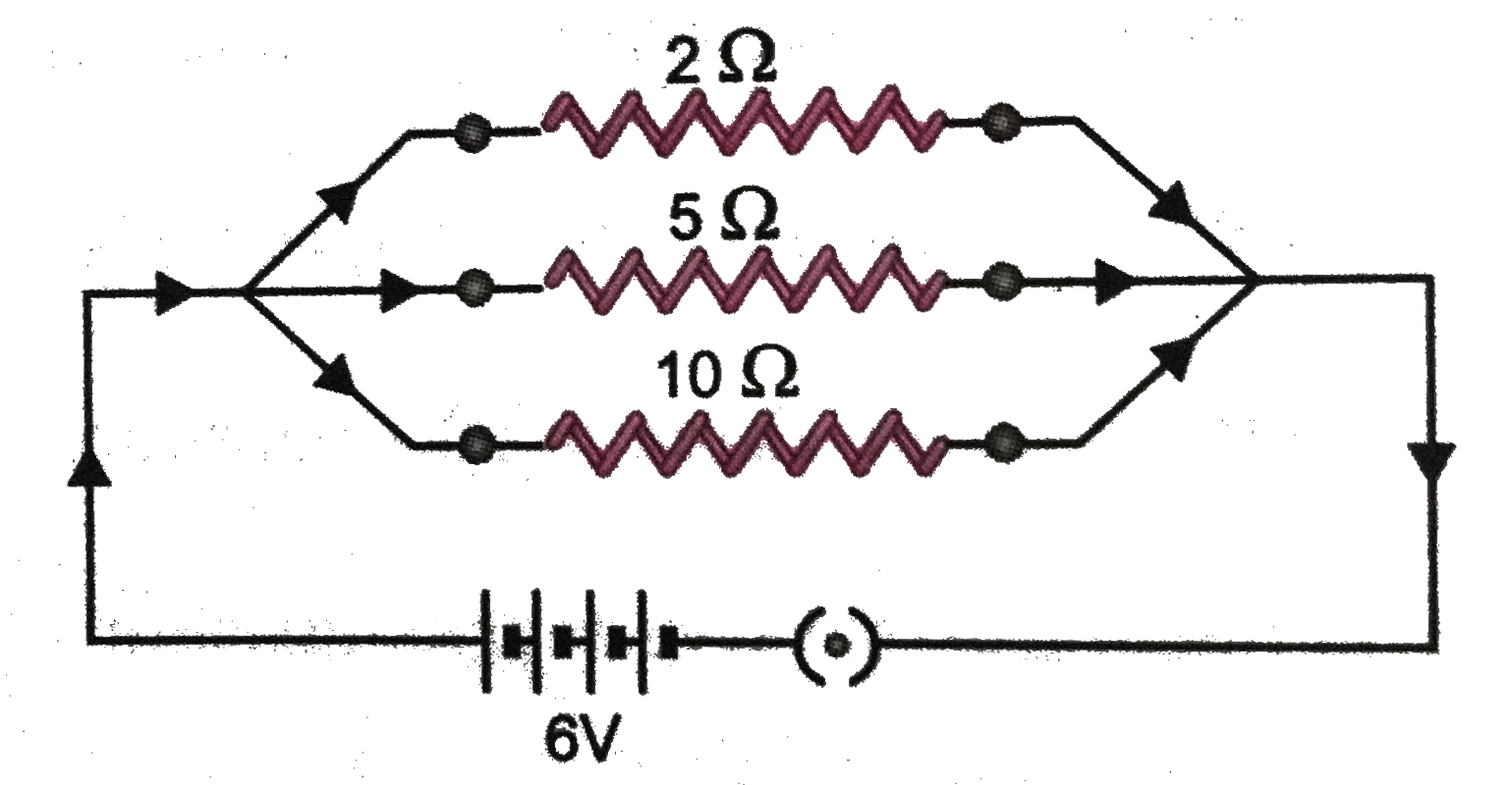 .
.
View Solution
Knowledge Check
In an experiment to find the equivalent resistance of two resistors connected in series, a student uses the circuit shown :
This circuit will give :
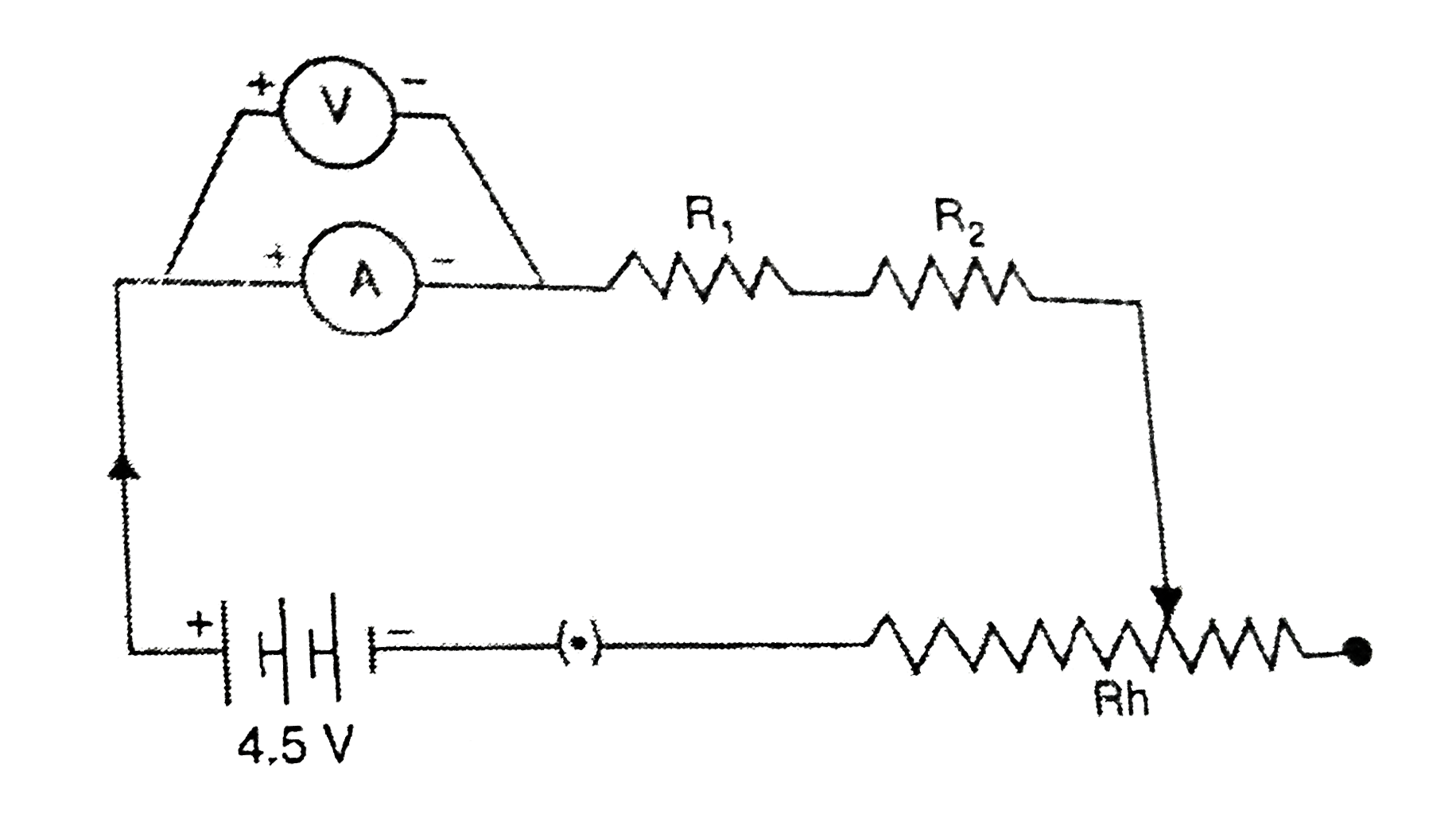 Acorrect reading for voltage V but incorrect reading for current IBcorrect reading for current I but incorrect reading for voltage (V)Ccorrect readings for both voltage V and current IDIncorrect readings for both current I and voltage V
For the circuit shown in the diagram below:
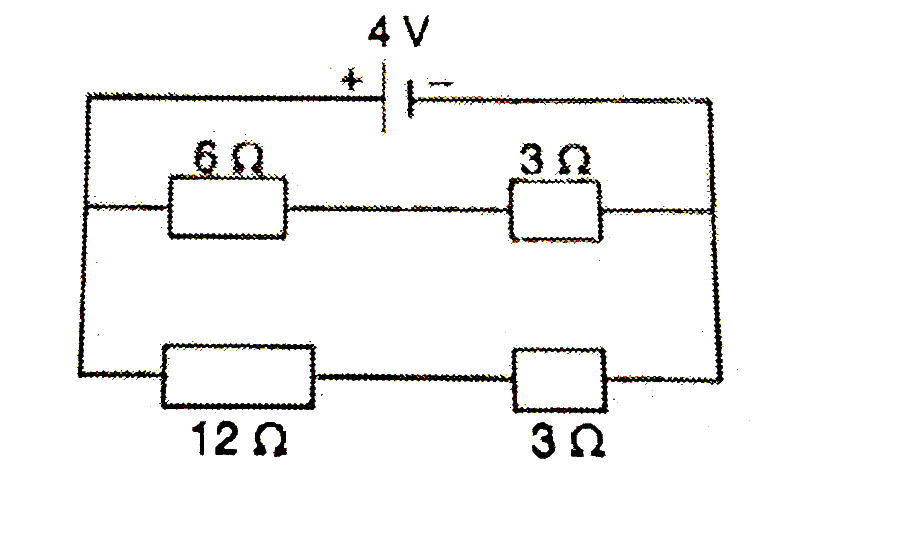
What is the value of:
(i) Current through 6Ω resistor?
(ii) potential difference across 12Ω resistor?A0.44 A , 3.2 VB0.22 A , 3.2 VC0.44 A , 6.4 VD0.11 A , 2.0 VFour student have made the following circuit diagrams for determining the equivalent resistance of two resistors connected in series :
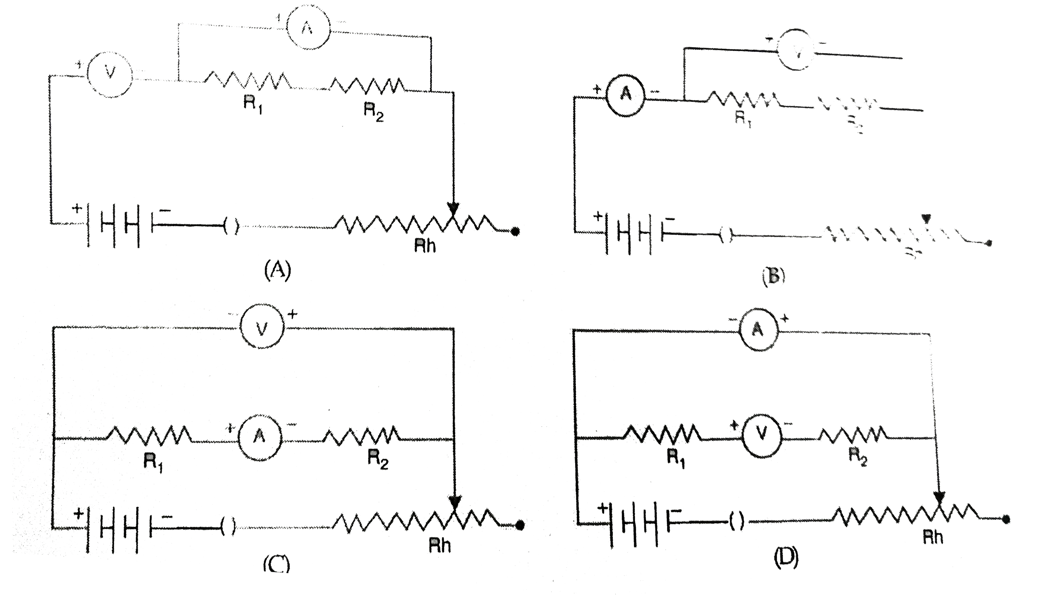
The correct circuit diagram is :AABBCCDD
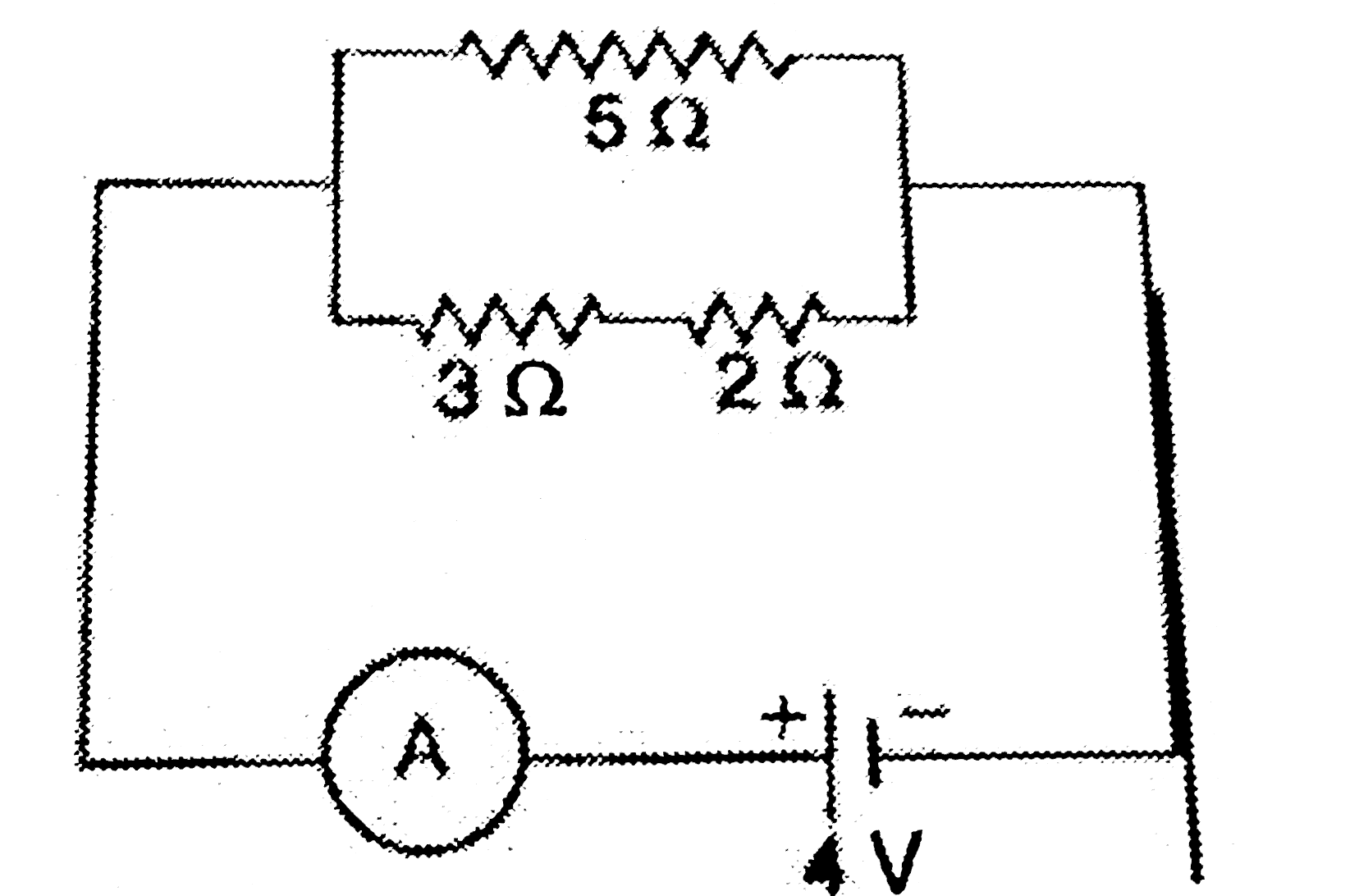
(a) With the help of a circuit diagram, obtain the relation for the equivalent resistance of two resistances connected in parallel.
(b) In the circuit diagram shown below, find:
(i) Total resistance.
(ii) Current shown by the ammeter A
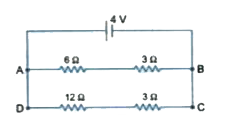
View SolutionFor the circuit shown in the given diagram:
What is the value of
(i) current through 6Ω resistor?
(ii) potential difference across 12Ω resistor?
View Solution(a) With the help of a circuit diagram, deduce the equivalent resistance of two resistances connected in series.
(b) Two resistances are connected in series as shown in the diagram:
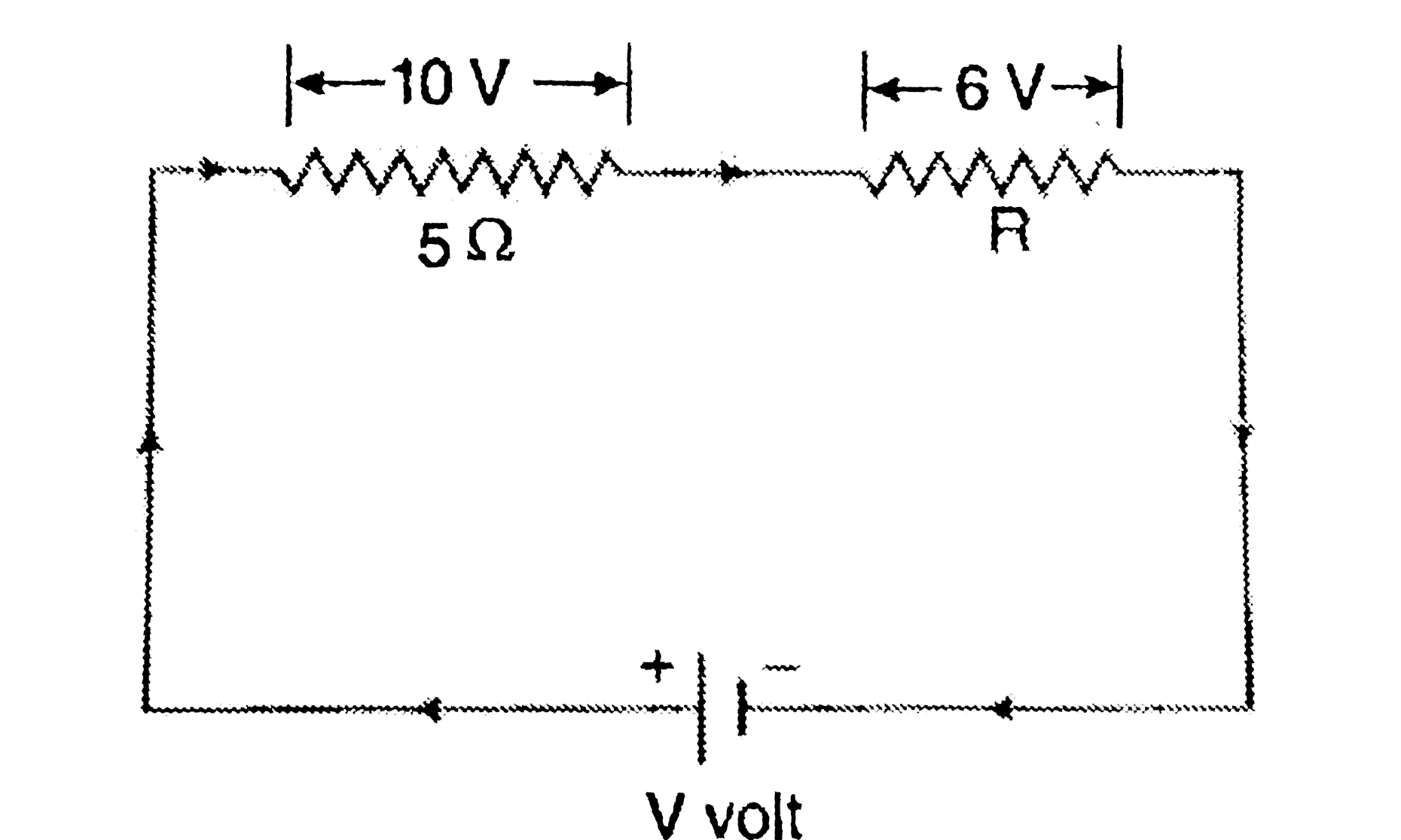
(i) What is the current through the 5 ohm resistance?
(ii) What is the current through R?
(iii) What is the value of R?
(iv) What is the value of V?
View SolutionDraw a schematic diagram of a circuit consisting of a battery of 3 cells of 2V each, a combination of three resistors of 10Ω,20Ω and 30Ω connected in a parallel, a plug key and an ammeter, all connected in series. Use the circuit to find the value of the following :
(a) current through each resistor
(b) total current in the circuit.
(c ) total effective resistance of the circuit.
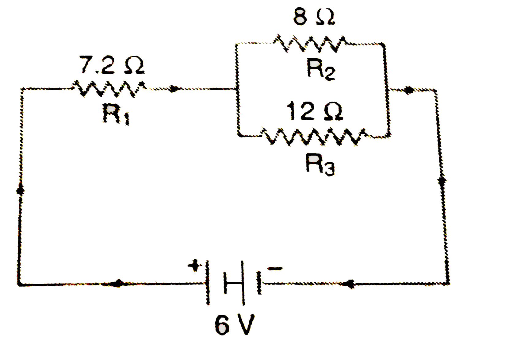
View SolutionIn the circuit diagram given alongside, find:
(i) total resistance of the circuit,
(ii) total current flowing in the circuit, and
(iii) the potential difference across R1
View Solution
