Consider the following four circuits P, Q, R and S which have been set up to find the resultant resistance of two resistors combined in parallel :
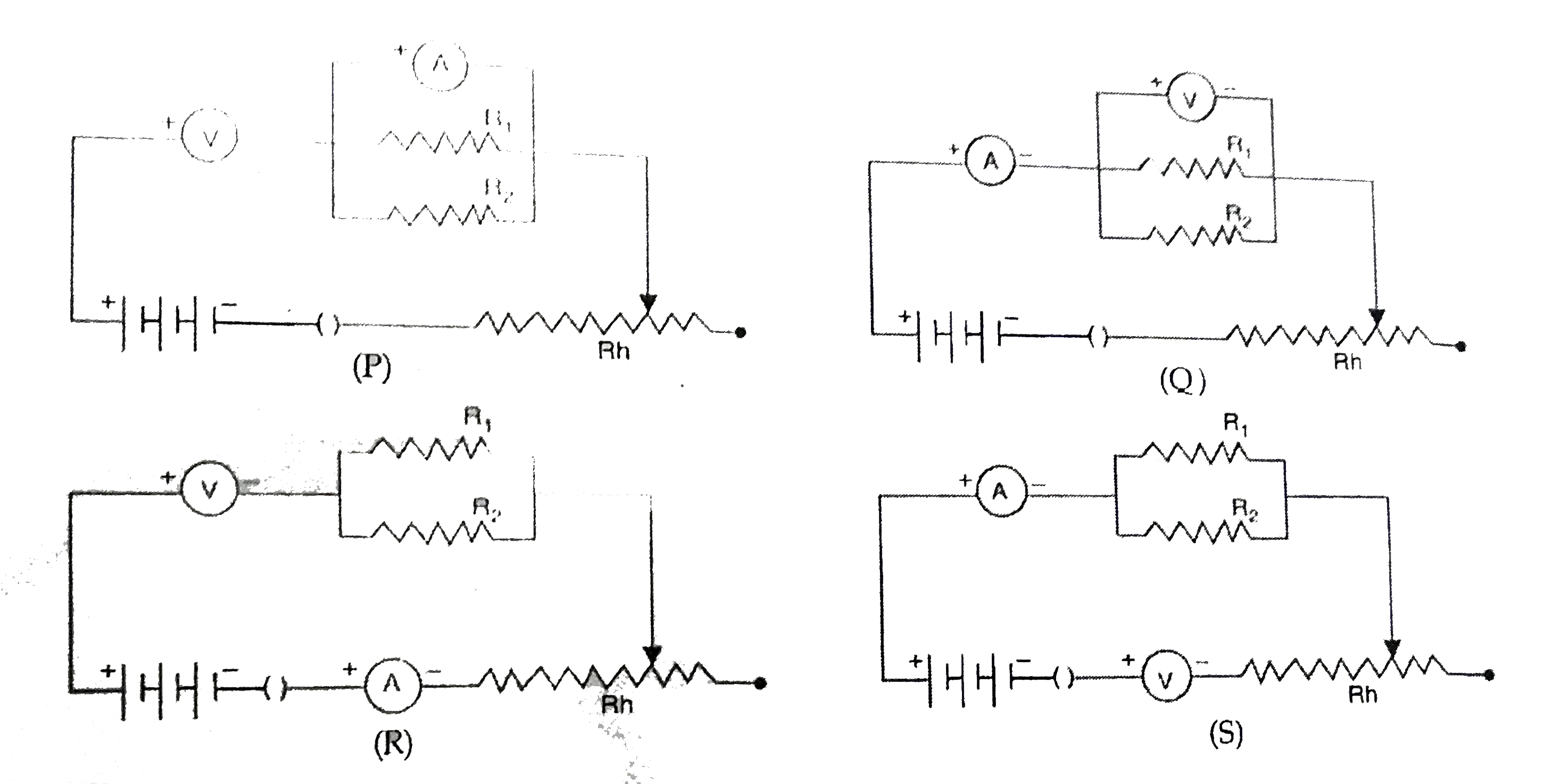
The correct way of connecting the ammeter and voltmeter in the circuit is :
P
Q
R
S
The correct Answer is:B
NA
Topper's Solved these Questions
- THE HUMAN EYE AND THE COLOURFUL WORLD BOOK - LAKHMIR SINGH & MANJIT KAURCHAPTER - THE HUMAN EYE AND THE COLOURFUL WORLD EXERCISE - Long Answer Type Question
3 Videos
- THE HUMAN EYE AND THE COLOURFUL WORLD BOOK - LAKHMIR SINGH & MANJIT KAURCHAPTER - THE HUMAN EYE AND THE COLOURFUL WORLD EXERCISE - NCERT Book
14 Videos
- THE HUMAN EYE AND THE COLOURFUL WORLD BOOK - LAKHMIR SINGH & MANJIT KAURCHAPTER - THE HUMAN EYE AND THE COLOURFUL WORLD EXERCISE - Long Answer Type Questions
2 Videos
- TEST PAPER 4BOOK - LAKHMIR SINGH & MANJIT KAURCHAPTER - TEST PAPER 4EXERCISE - SECTION A
10 Videos
Similar Questions
Drive expression for the total resistance of a circuit in which a few resistors are connected in parallel.
View SolutionTwo students made two circuits A and B to determine the resultant resistance of two resistors R1 and R2 connected in series :
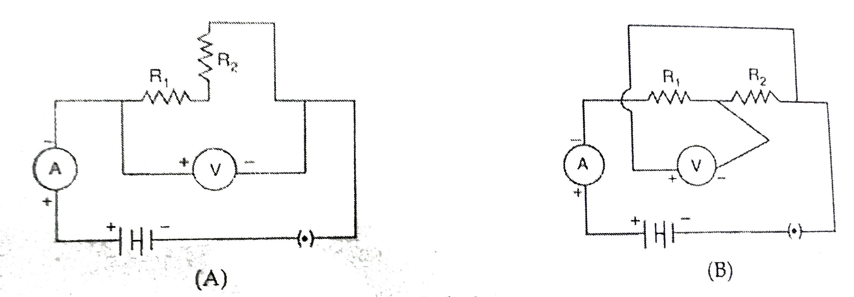
All the components have been connected correctly in :
View Solution
Knowledge Check
To study the dependence of current (I) on the potential difference (V) across a resistor, the correct way of connecting the ammeter and voltmeter in the circuit is :
Aammeter and voltmeter both are connected in seriesBammeter is connected in parallel and voltmeter in seriesCammeter is connected in series and voltmeter in parallelDammeter and voltmeter both are connected in parallelFour student have made the following circuit diagrams for determining the equivalent resistance of two resistors connected in series :
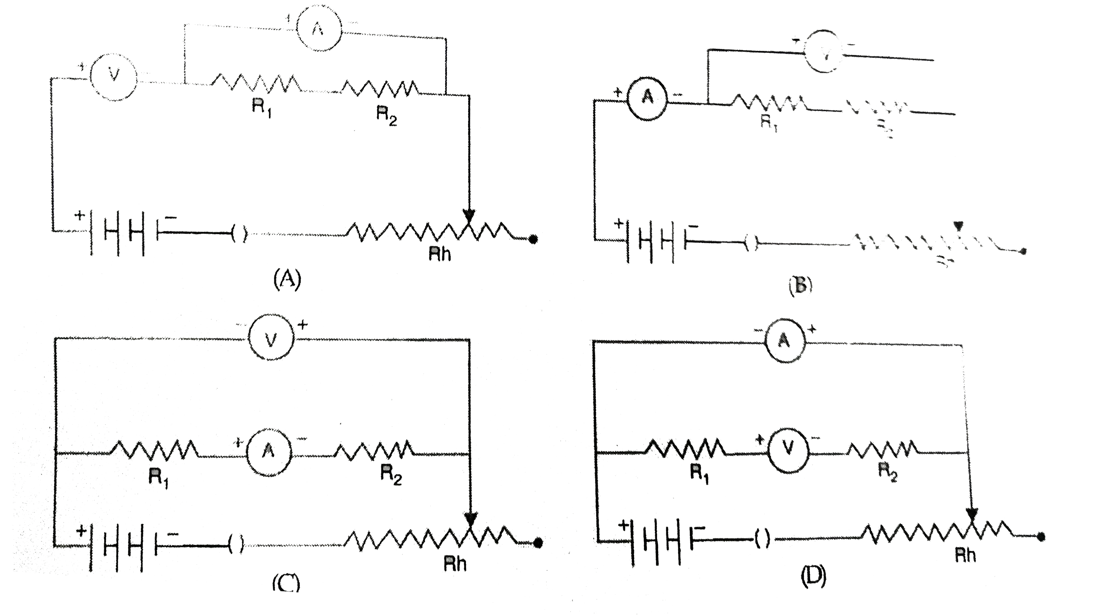
The correct circuit diagram is :AABBCCDDIn an experiment to find the equivalent resistance of two resistors connected in series, a student uses the circuit shown :
This circuit will give :
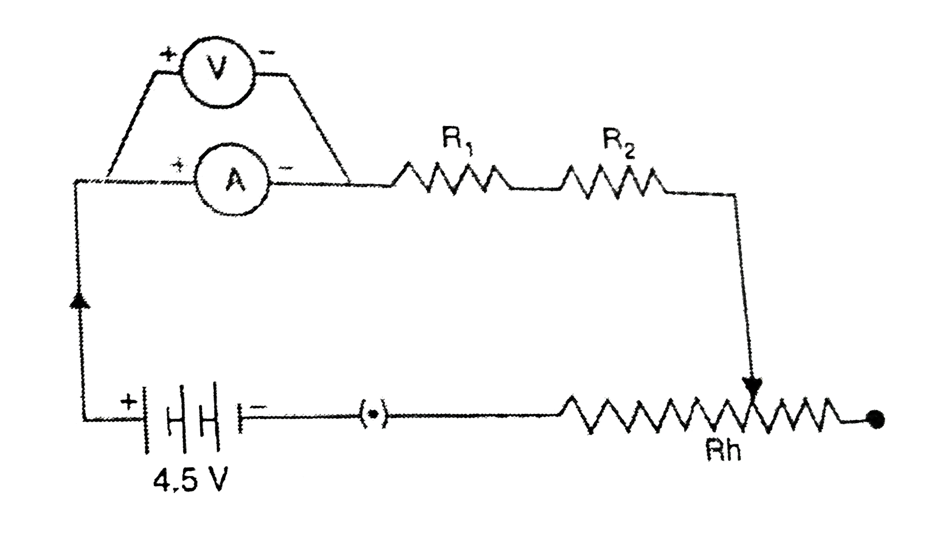 Acorrect reading for voltage V but incorrect reading for current IBcorrect reading for current I but incorrect reading for voltage (V)Ccorrect readings for both voltage V and current IDIncorrect readings for both current I and voltage V
A student stes up an electric circuit shown here for finding the equivalent resistance of two resistors in series :
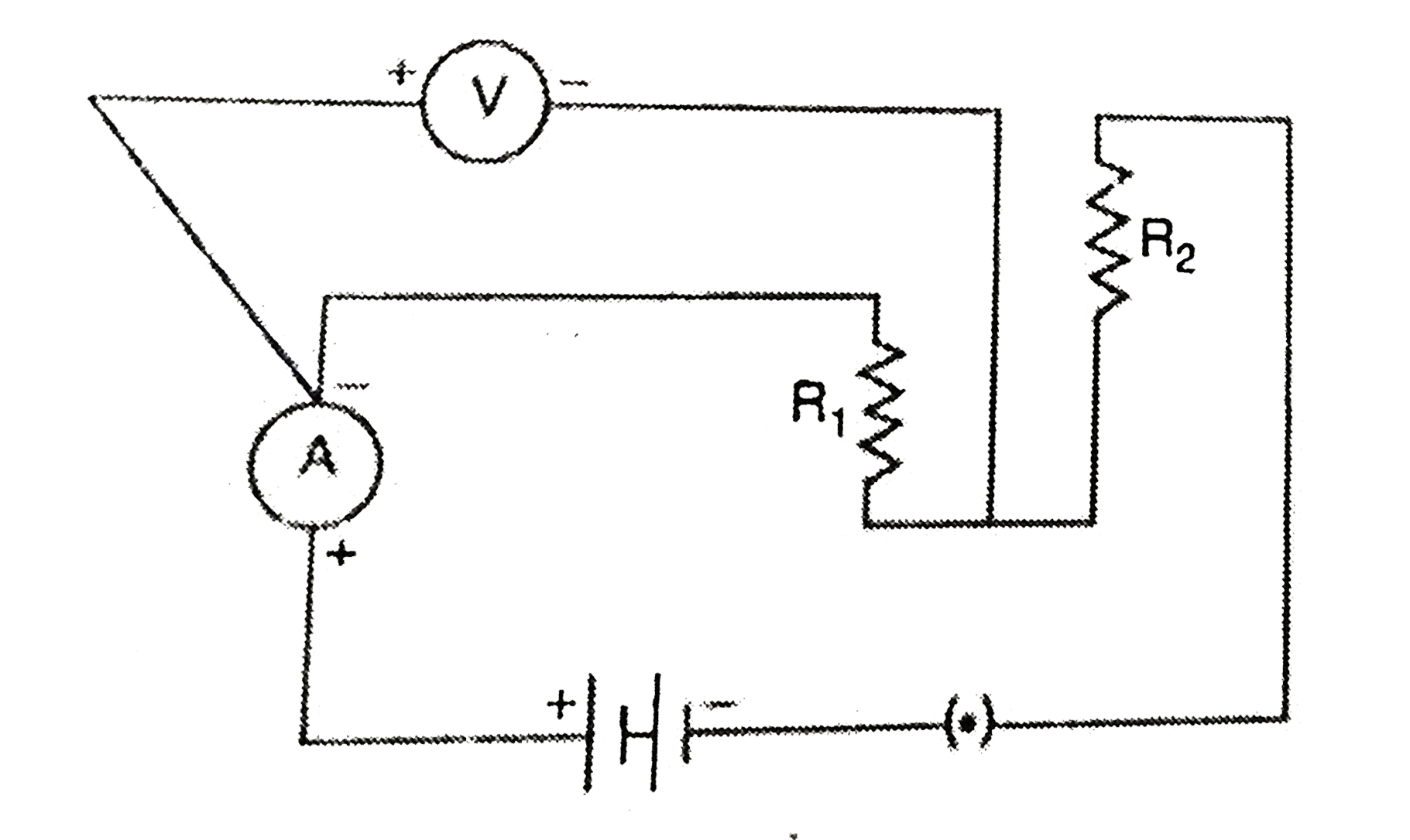
In this circuit, the :
View SolutionThe following four circuits have been made for studying the dependence of current on the potential difference across a resistor.
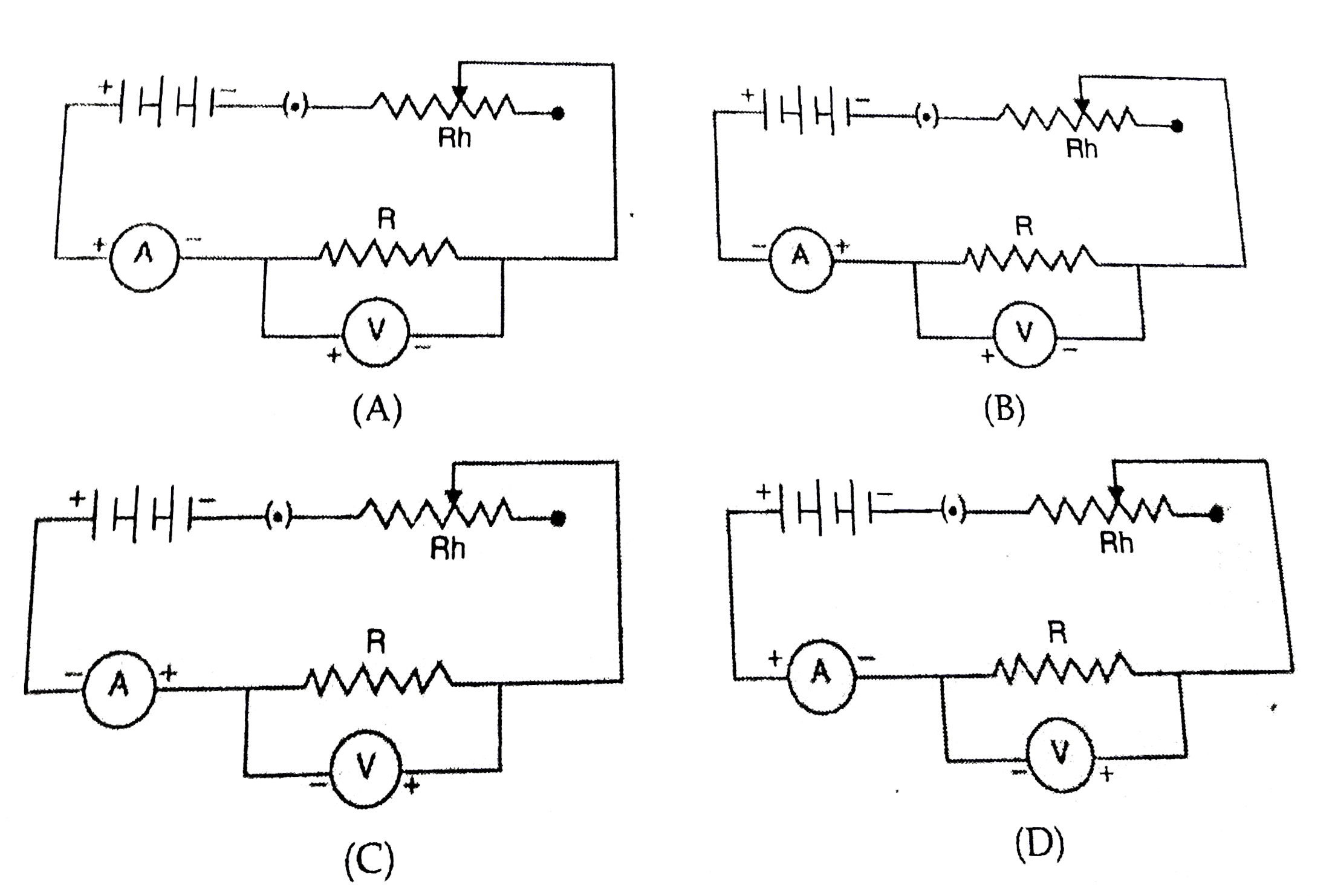
The correct circuit is :
View SolutionA student while performing the experiment to find the resultant resistance of two resistors connected in series observes the ammeter pointer at position P when the key is 'off' and the same pointer at position Q when the key is 'on'.
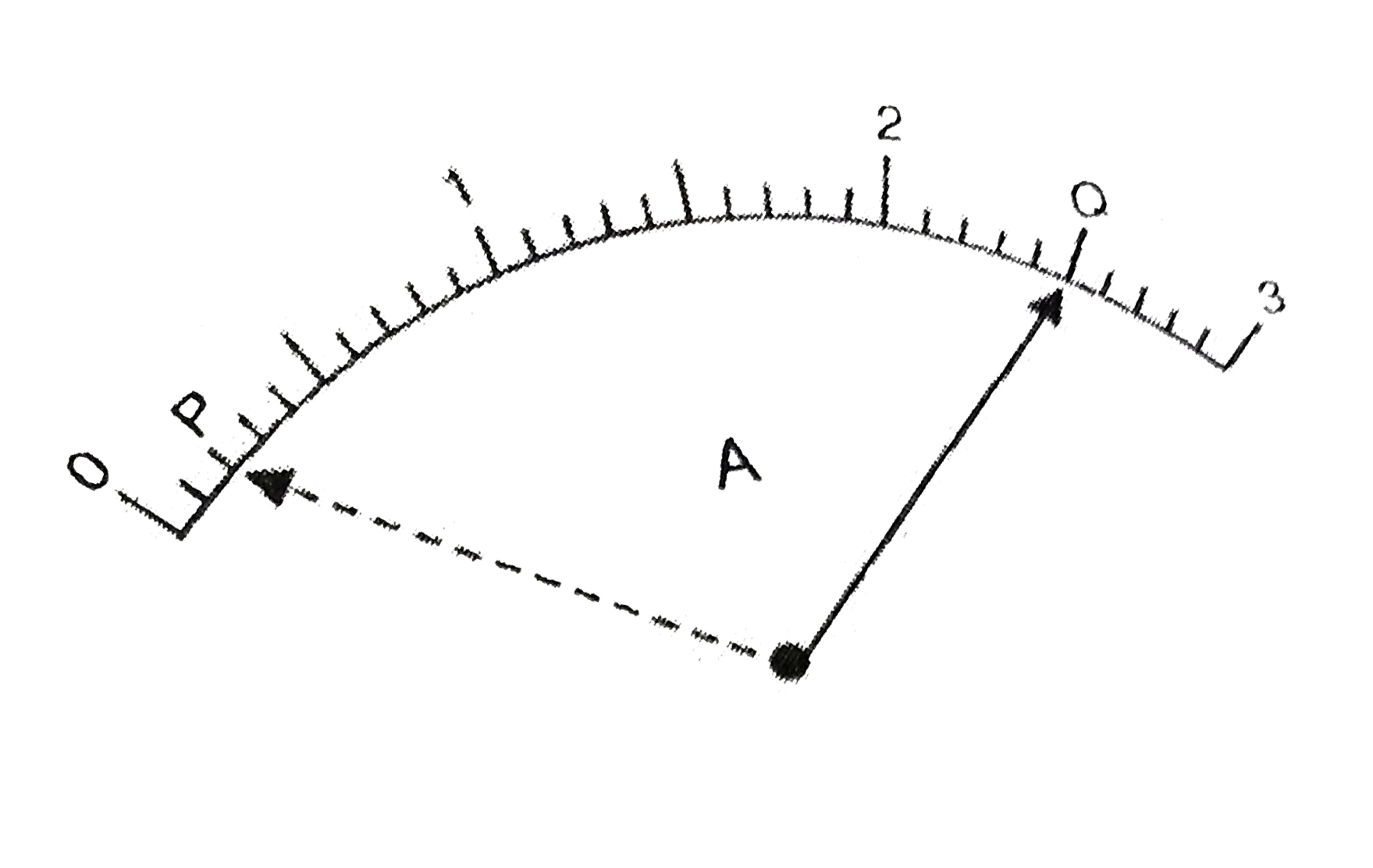
The correct reading of ammeter is :
View SolutionStudy the following circuit and answer any four questions given below:
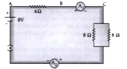
What will be the effective resistance of two 8Ω resistors in the combination?
View SolutionIn the experiment on finding the equivalent resistance of two resistors, connected in parallel, three students connected the voltmeter in their circuits, in the three ways X, Y and Z shown here.
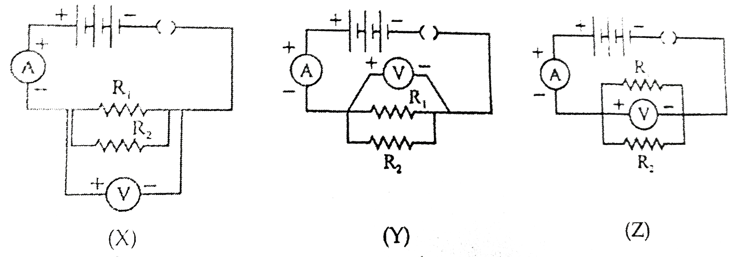
The voltmeter has been correctly connected in
View Solution
