Five long wires A, B, C, D and E, each carrying current I are arranged to form edges of a pentagonal prism as shown in figure. Each carries current out of the plane of paper.
(a) What will be magnetic induction at a point on the axis O? Axis is at a distance R from each wire.
(b) What will be the field if current in one of the wires (say A) is switched off?
(c) What if current in one of the wire (say) A is reversed?
To solve the given problem, we will analyze the magnetic induction at a point on the axis of a pentagonal prism formed by five long wires carrying current out of the plane of the paper.
Part (a): Magnetic Induction at Point O
1. Identify the Contribution from Each Wire:
Each wire (A, B, C, D, E) contributes to the magnetic field at point O. The magnetic field due to a long straight wire carrying current I at a distance R from the wire is given by the formula:
B=μ0I2πR
where μ0 is the permeability of free space.
2. Determine the Direction of Magnetic Fields:
Using the right-hand rule, we can determine the direction of the magnetic field produced by each wire. Since all currents are out of the plane of the paper, the magnetic fields at point O will have specific directions based on their positions.
3. Calculate the Resultant Magnetic Field:
The magnetic fields from wires B and E will cancel each other out because they are equal in magnitude and opposite in direction. Therefore, we only need to consider the contributions from wires A, C, and D:
BO=BA+BC+BD
Since BB=−BE, we can simplify:
BO=BA+BC+BD=BA−BE+BC+BD
Noting that BC+BD=−BA (due to symmetry), we find:
BO=BA−BA=0
Thus, the total magnetic induction at point O is zero.
Part (b): Magnetic Field with Wire A Switched Off
1. Recalculate the Magnetic Field:
If wire A is switched off, we only consider the contributions from wires B, C, D, and E.
2. Identify the Remaining Contributions:
The contributions from wires B and E will still cancel each other out:
BO=BB+BC+BD+BE
Since BB=−BE, we have:
BO=BC+BD
From symmetry, BC+BD=−BA (as before), but now we only have:
BO=−BA
Thus, the magnetic field at point O due to the remaining wires is:
BO=−μ0I2πR
This magnetic field is directed towards the left.
Part (c): Magnetic Field with Current in Wire A Reversed
1. Recalculate the Magnetic Field with Reversed Current:
When the current in wire A is reversed, its contribution will change direction. Thus, we have:
BO=−BA+BB+BC+BD+BE
2. Substituting Known Values:
Since BB=−BE, we can simplify:
BO=−BA+BC+BD
Again, from symmetry, we know:
BC+BD=−BA
Therefore, we can substitute:
BO=−BA−BA=−2BA
This gives:
BO=−2(μ0I2πR)=−μ0IπR
The direction of this field is also towards the left.
Summary of Results:
- (a) Magnetic induction at point O: 0
- (b) Magnetic field if wire A is switched off: −μ0I2πR (towards left)
- (c) Magnetic field if current in wire A is reversed: −μ0IπR (towards left)
Each wire (A, B, C, D, E) contributes to the magnetic field at point O. The magnetic field due to a long straight wire carrying current I at a distance R from the wire is given by the formula:
B=μ0I2πR
where μ0 is the permeability of free space.
Using the right-hand rule, we can determine the direction of the magnetic field produced by each wire. Since all currents are out of the plane of the paper, the magnetic fields at point O will have specific directions based on their positions.
The magnetic fields from wires B and E will cancel each other out because they are equal in magnitude and opposite in direction. Therefore, we only need to consider the contributions from wires A, C, and D:
BO=BA+BC+BD
Since BB=−BE, we can simplify:
BO=BA+BC+BD=BA−BE+BC+BD
Noting that BC+BD=−BA (due to symmetry), we find:
BO=BA−BA=0
Thus, the total magnetic induction at point O is zero.
If wire A is switched off, we only consider the contributions from wires B, C, D, and E.
The contributions from wires B and E will still cancel each other out:
BO=BB+BC+BD+BE
Since BB=−BE, we have:
BO=BC+BD
From symmetry, BC+BD=−BA (as before), but now we only have:
BO=−BA
Thus, the magnetic field at point O due to the remaining wires is:
BO=−μ0I2πR
This magnetic field is directed towards the left.
When the current in wire A is reversed, its contribution will change direction. Thus, we have:
BO=−BA+BB+BC+BD+BE
Since BB=−BE, we can simplify:
BO=−BA+BC+BD
Again, from symmetry, we know:
BC+BD=−BA
Therefore, we can substitute:
BO=−BA−BA=−2BA
This gives:
BO=−2(μ0I2πR)=−μ0IπR
The direction of this field is also towards the left.
- (a) Magnetic induction at point O: 0
- (b) Magnetic field if wire A is switched off: −μ0I2πR (towards left)
- (c) Magnetic field if current in wire A is reversed: −μ0IπR (towards left)
Topper's Solved these Questions
- MOVING CHARNGES AND MAGNETISMBook:NCERT EXEMPLAR ENGLISHChapter:MOVING CHARNGES AND MAGNETISMExercise:Short Answer Type Question
Explore 6 Videos
- MAGNETISM AND MATTER Book:NCERT EXEMPLAR ENGLISHChapter:MAGNETISM AND MATTER Exercise:All Questions
Explore 24 Videos
- NUCLEIBook:NCERT EXEMPLAR ENGLISHChapter:NUCLEIExercise:Long answer type question
Explore 10 Videos
Similar Questions
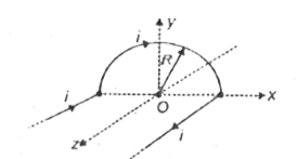
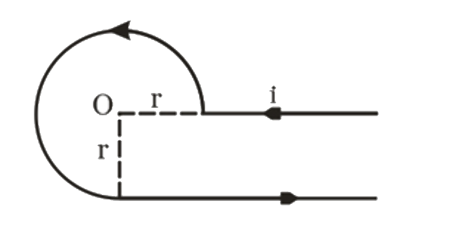
The magnetic induction at the point O, if the wire carries a current I, is
View SolutionA long wire carrying a current i is bent to form a plane angle alpha.Find the magnetic field B at a point on the bisector of this angle situated at a distance x from the vertex.
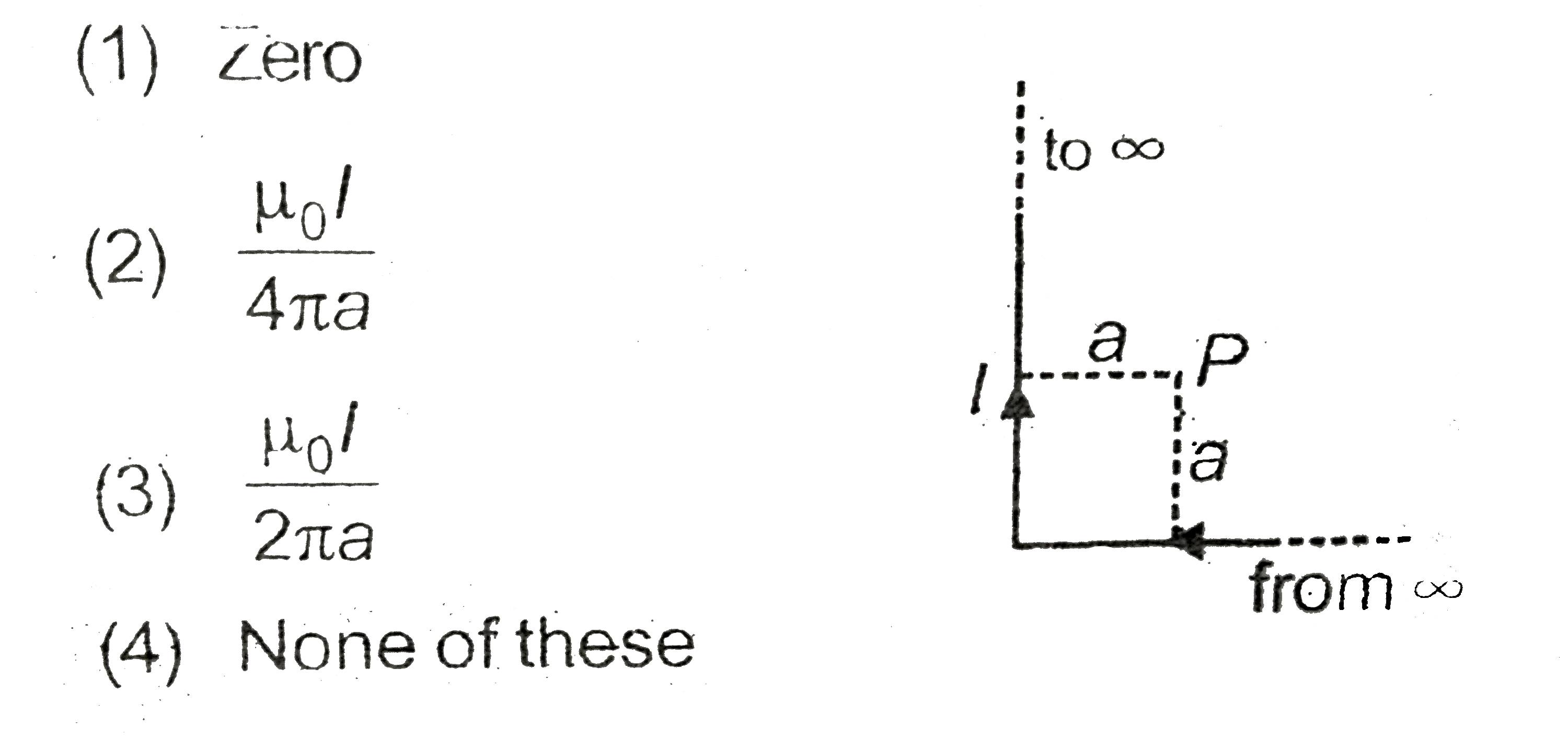
View SolutionA wire of infinite length bent as shown in figure carries current l. What is the magnetic field at the point P ?
View SolutionA circular coil of wire of radius 'r' has 'n' turns and carries a current 'I'. The magnetic induction (B) at a point on the axis of the coil at a distance √3r from its centre is
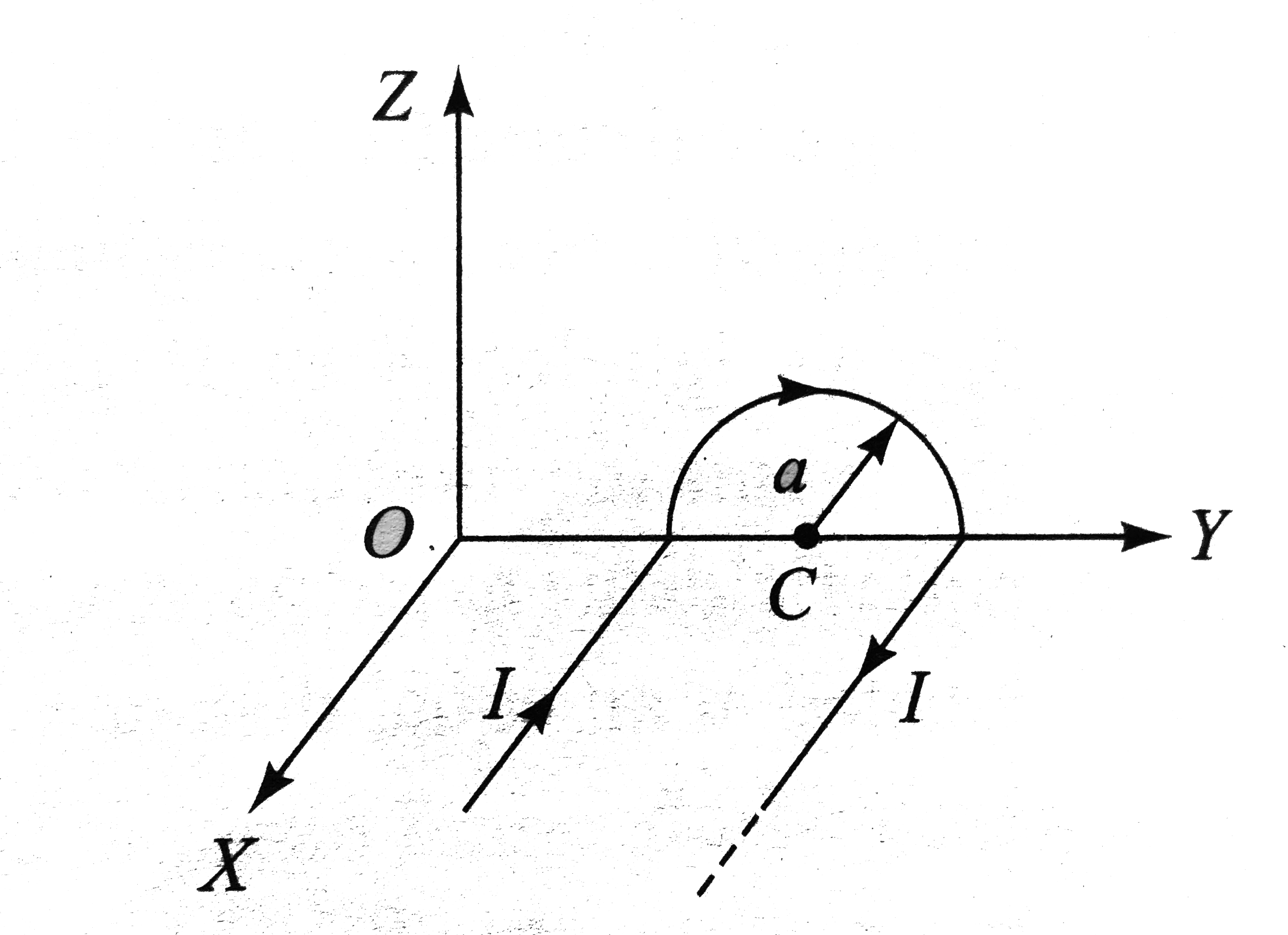
View SolutionA long wire bent as shown in fig. carries current I. If the radius of the semicircular portion is a, the magnetic field at centre C is
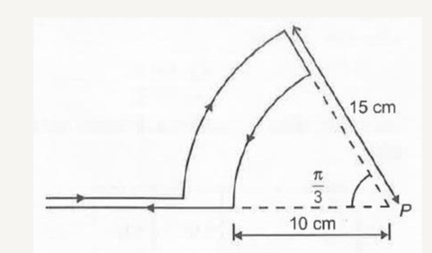
View SolutionThe segment of wire shown in figure carries a current of i=5 A. The magnetic field (in Tesla) at the point P is
View SolutionFind the magnetic induction at point O, if the current carrying wire is in the shape shown in the figure.
View SolutionA long straight wire carries a current of 35A. What is the magnitude of the field →B at a point 20cm from the wire?
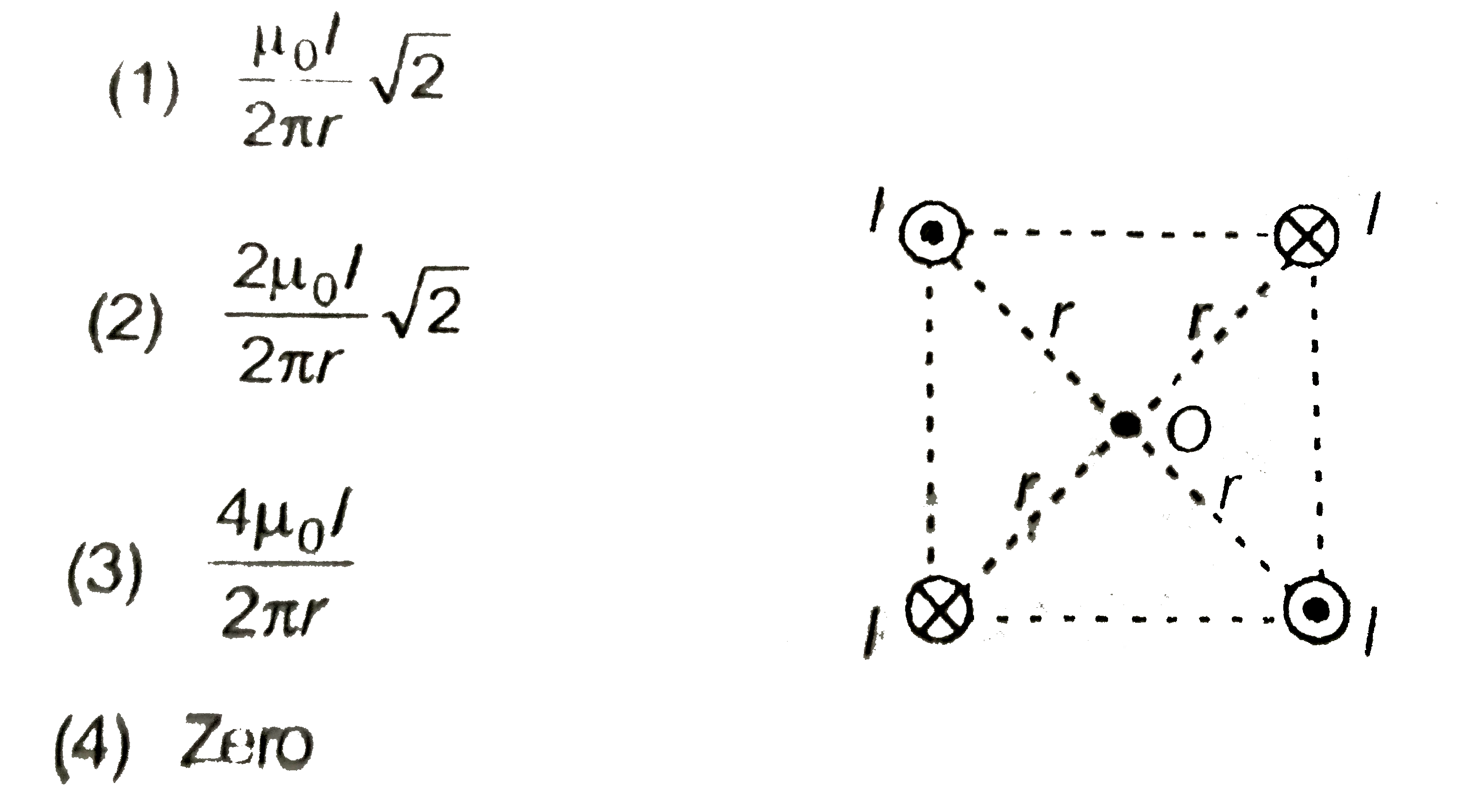
View SolutionFigure shows an arrangement in which long parallel wires carrying equal currents into or out of the page of paper at the corners of a square. The magnetic field at the centre of square is
View SolutionA part of a long wire carrying a current i is bent into a circle of radius r as shown in figure. The net magnetic field at the centre O of the circular loop is :

View Solution

