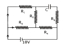
In the circuit shown in fig. the cell is ideal with emf 15V. Each resistance is of 3Ω. The potential difference across the capacitor in steady state is
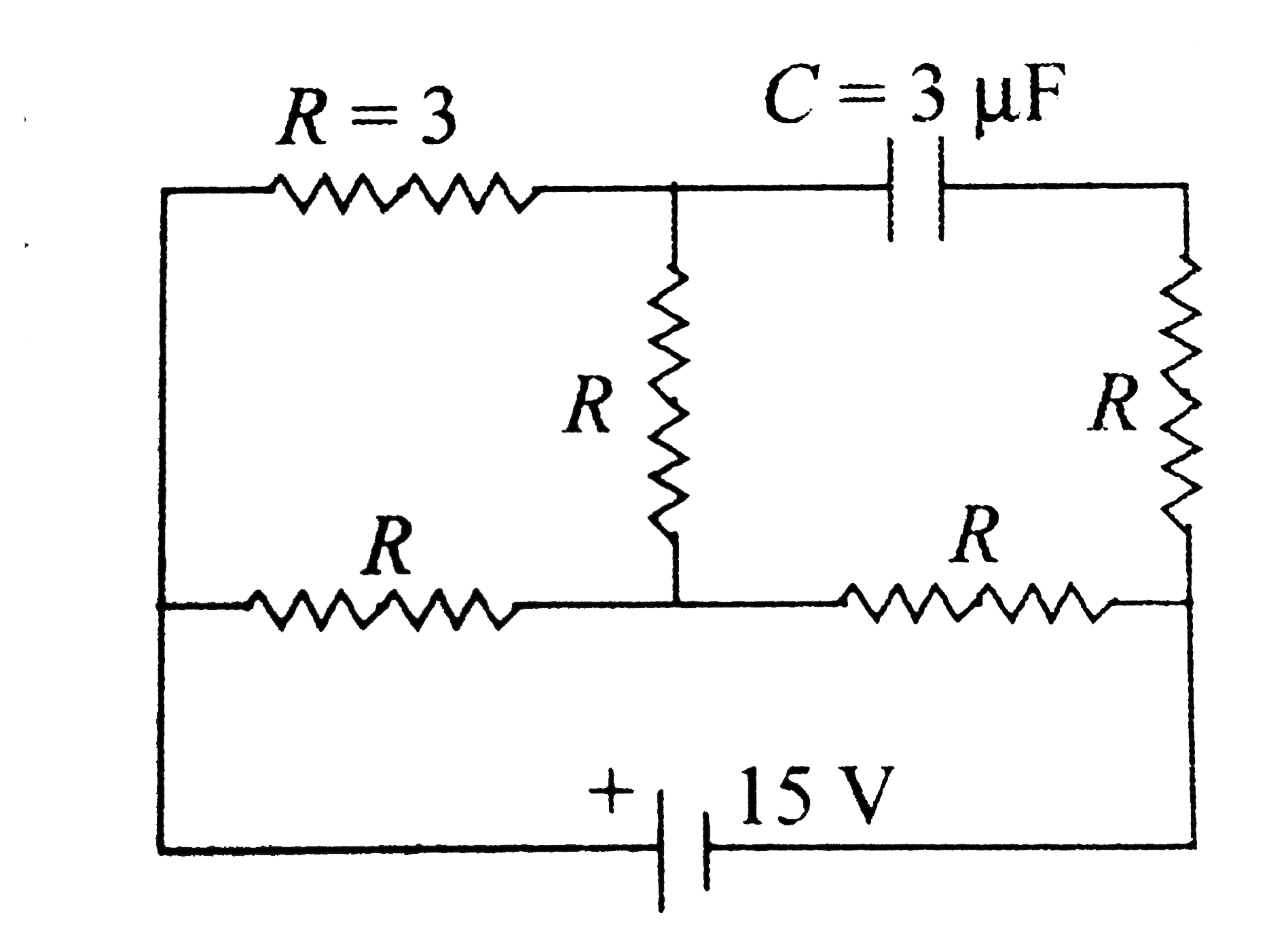
zero
9V
12V
15V
The correct Answer is:C
Step by step video, text & image solution for In the circuit shown in fig. the cell is ideal with emf 15V. Each resistance is of 3Omega. The potential difference across the capacitor in steady state is by Physics experts to help you in doubts & scoring excellent marks in Class 12 exams.
Updated on:21/07/2023Topper's Solved these Questions
Similar Questions
Knowledge Check
In the circuit shown in fig. the cell is ideal with emf 15V. Each resistance is of 3Ω. The potential difference across the capacitoro in steady state is
 A0B9 VC12 VD15 V
In the circuit shown, the cell is ideal , with emf=15V. Ecah resistance is of 3Ω. the potential difference across the capacitor is
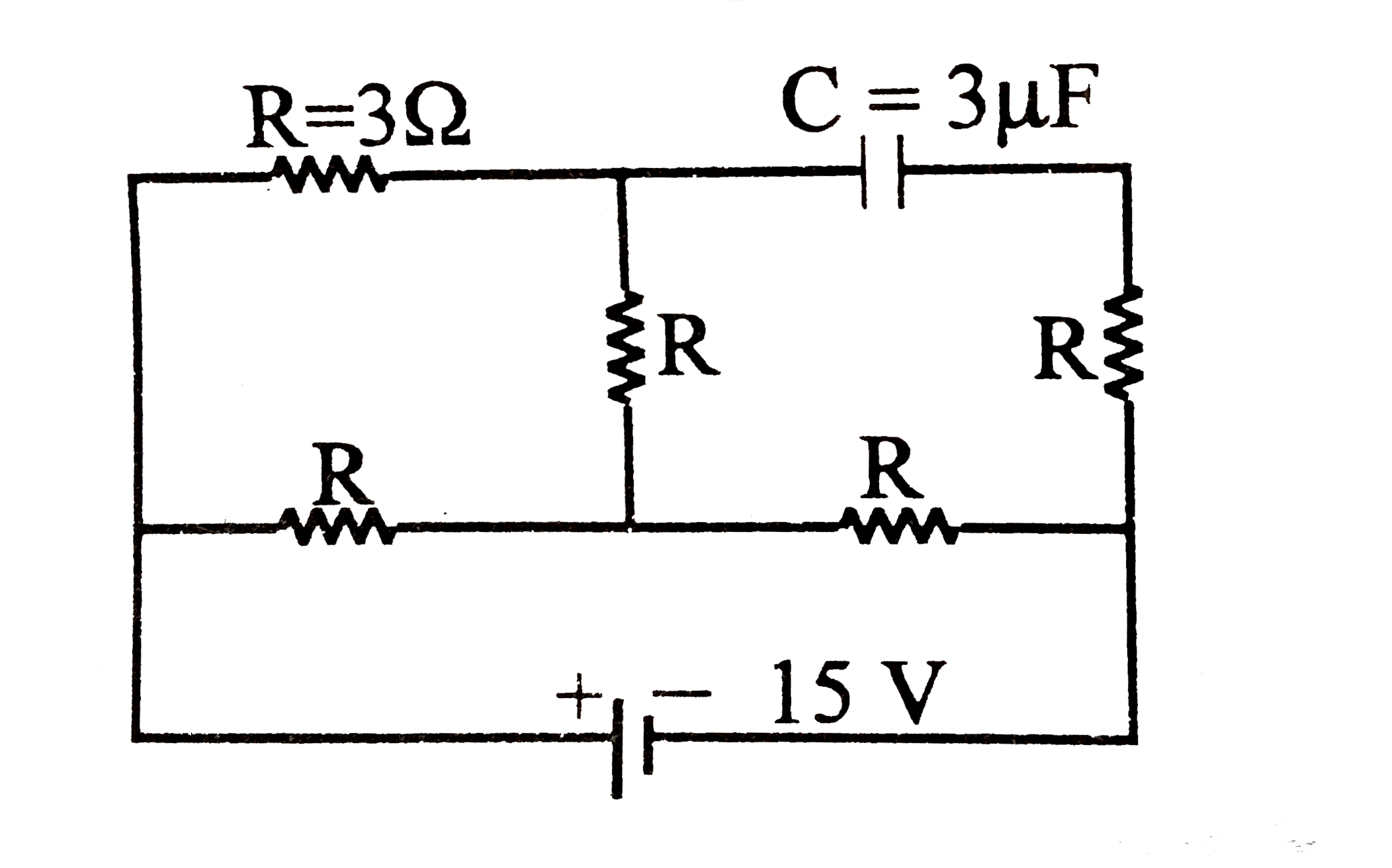 AzeroB9VC12VD15V
In the circuit shown the cell is idea with end =15V each resistance is of 3Ω The potential difference the capacitor is
 AzeroB9VC12VD15V
An ideal cell of emf 10 V is connected in circuit shown in figure. Each resistance is 2Ω . The potential difference (in V) across the capacitor when it is fully charged is _______.
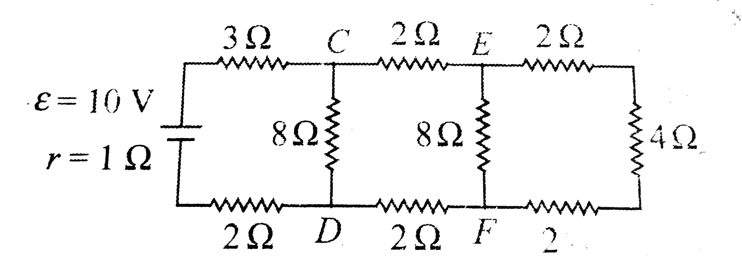
View SolutionIn the circuit shown in fig. the cell has emf 10V and internal resistance 1Ω
View SolutionIn the fig. shown the circuit is in steady state.
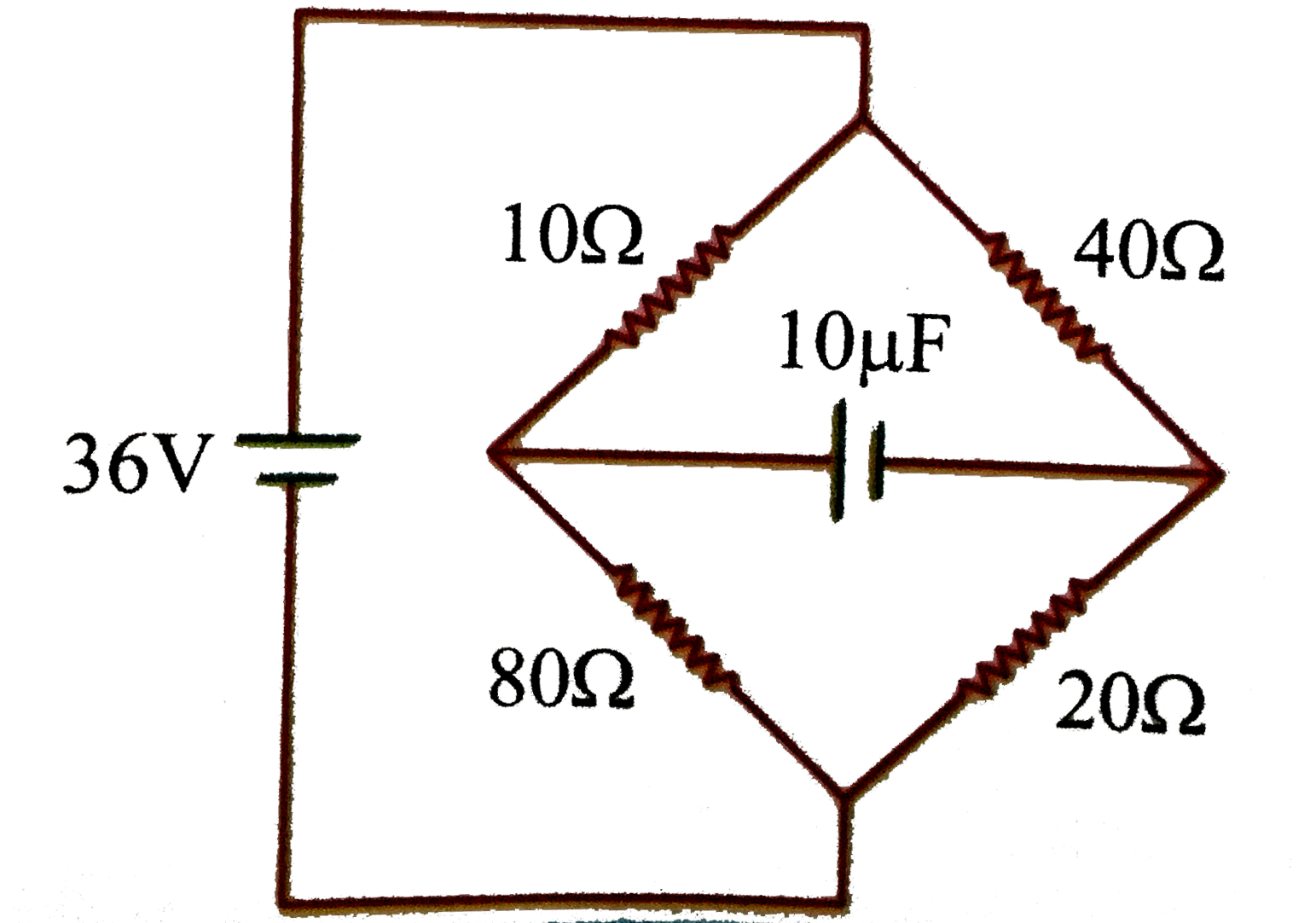
what is the potential difference across the capacitor in steady state ?
View SolutionA capacitor of capacitance 1μF is connected in parallel with a resistance 10Ω and the combination is connected across the terminals of a battery of EMF 50 V and internal resistance 1Ω. The potential difference across the capacitor at steady state is (in Volt)
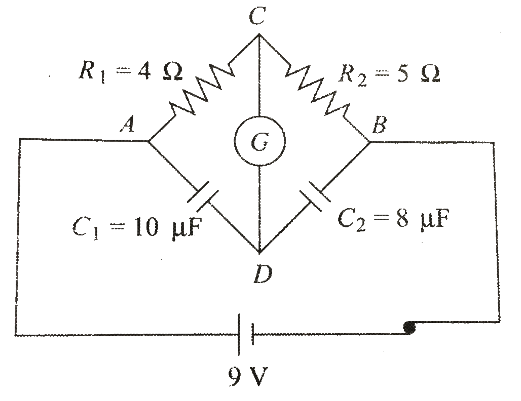
View SolutionIn the circuit shows in Fig. 6.63, the cell is ideal with emf 9V. If the resistance of the coil of galvanometer is 1Ω, then
View Solution


