In the circuit shows in Fig. 6.63, the cell is ideal with emf 9V. If the resistance of the coil of galvanometer is 1Ω, then
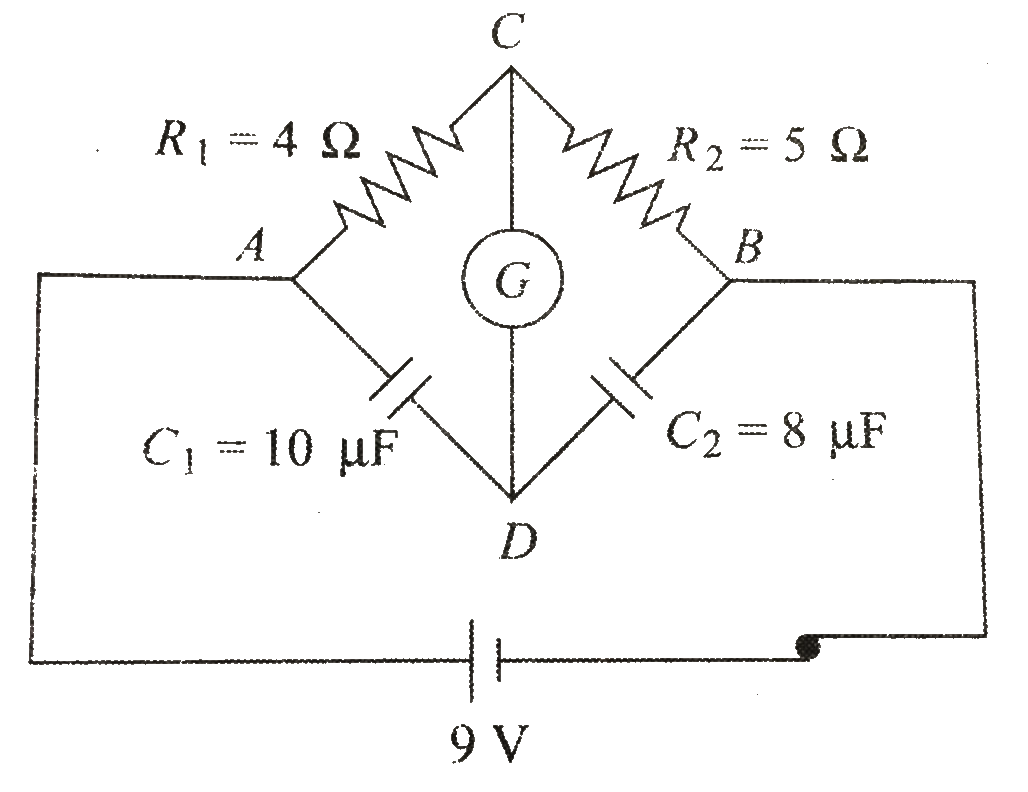
no current flows in the galvanometer
charge flowing through 8μF is 40μC
potential difference across 10μF is 5V
potential difference across 10μF is 4V
The correct Answer is:A, B, D
Since R1/R2=C2/C1, the wheatstone bridge is balanced.
Hence, VC=VD. No current passes through the galvanometer.
Hence, option (a) is correct.
Potential difference across R1= potential difference across
C1=4V
Potential difference across R2= potential difference across
C2=5V
Potential difference across 5Ω is the potential difference across 8μF capacitor. So, charge across 8μF capacitor is
Q=CV=8μF×5V=40μC. hence, option (b) is correct and so is option(d).
Topper's Solved these Questions
- ELECTRICAL MEASURING INSTRUMENTSBOOK - CENGAGE PHYSICSCHAPTER - ELECTRICAL MEASURING INSTRUMENTSEXERCISE - Assertion-Reasoning
7 Videos
- ELECTRICAL MEASURING INSTRUMENTSBOOK - CENGAGE PHYSICSCHAPTER - ELECTRICAL MEASURING INSTRUMENTSEXERCISE - Comprehansion
15 Videos
- ELECTRICAL MEASURING INSTRUMENTSBOOK - CENGAGE PHYSICSCHAPTER - ELECTRICAL MEASURING INSTRUMENTSEXERCISE - Single Correct
94 Videos
- ELECTRIC POTENTIALBOOK - CENGAGE PHYSICSCHAPTER - ELECTRIC POTENTIALEXERCISE - DPP 3.5
14 Videos
- ELECTROMAGENTIC INDUCTIONBOOK - CENGAGE PHYSICSCHAPTER - ELECTROMAGENTIC INDUCTIONEXERCISE - QUESTION BANK
40 Videos
Similar Questions
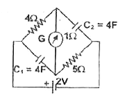
In the circuit shown below the cell is ideal, with emf = 2 V: The resistance of the coil of the galvanometer G is 1Ω. Then, find the potential difference across C1 (in volts), in steady state
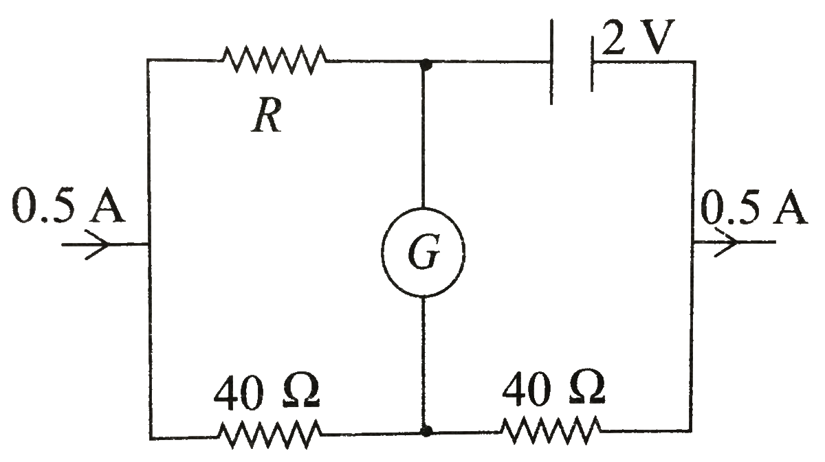
View SolutionIn the circuit shows in Fig. 6.74, the internal resistance of the cell is negligible. For the value of R=40/xΩ, no current flows through the galvanometer. What is x?
View Solution
Knowledge Check
In the circuit shown, the cell is ideal with emf = 2V . The resistance of the coil of the galvanometer G is 1Ω.

(i) No current flows in G
(ii) 0.2A current flows in G
(iii) potential difference across C1is1V
(iv) Potential difference across C2 is 1.2VA(i),(iii)B(i),(ii),(iv)C(ii),(iii),(iv)D(i),(ii),(iv)In the circuit shown in fig. the cell is ideal with emf 15V. Each resistance is of 3Ω. The potential difference across the capacitoro in steady state is
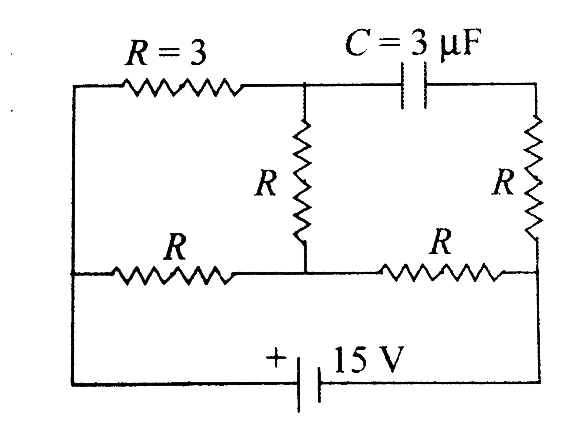 A0B9 VC12 VD15 V
In the circuit shown in fig. the cell has emf 10V and internal resistance 1Ω
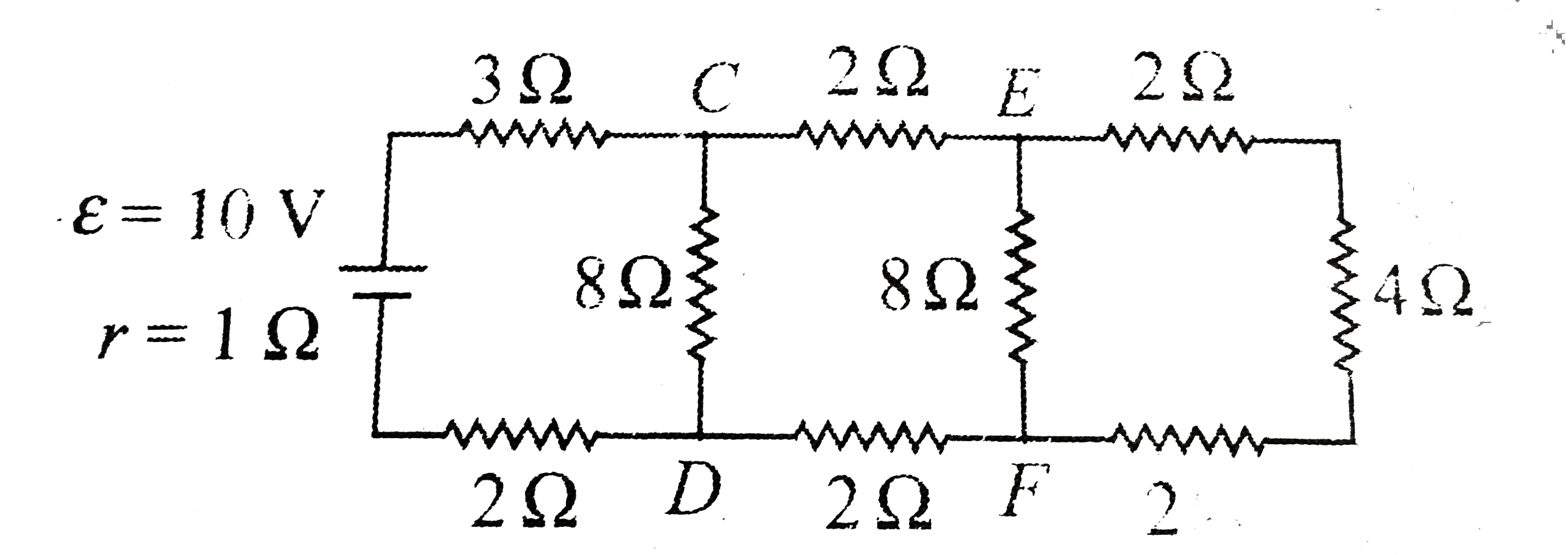 AThe current through the 3Ω resistor is 1A.BThe currents through the 3Ω resistor is 0.5 A.CThe currents through the 4Ω resistor is 0.5 ADThe current through the 4Ω resistor is 0.25 A.
In the circuit shown in Fig. the emf of the sources is equal to ξ=5.0V and the resistances are equal to R1=4.0Ω and R2=6.0Ω. The internal resistance of the source equals R=1.10Ω. Find the currents flowing through the resistances R1 and R2.

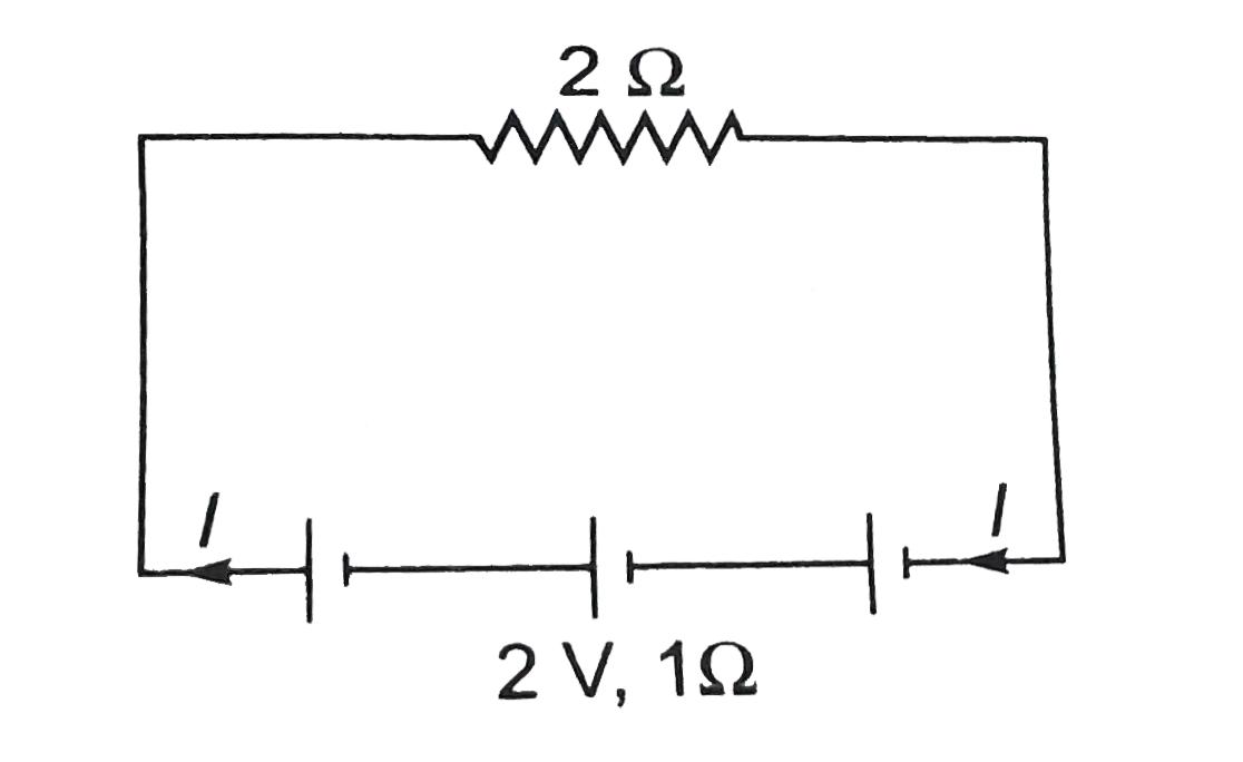
View SolutionIn the electric circuit shown each cell has an emf of 2 V and internal resistance of 1Ω. The external resistance is 2Ω . The value of the current is (in A)
View SolutionIn the circuit shown in Fig. 4.63, the terminal voltage of the battery is 6.0 V. Find the current I through the 18Ω resistor.
View SolutionDraw the circuit diagram to verify Ohm's Law with the help of a main resistance of 100Ω and tow galvanometer of resistance 106Ωand10−3Ω and a source of varying emf.
Show the correct positions of volmeter and ammeter.
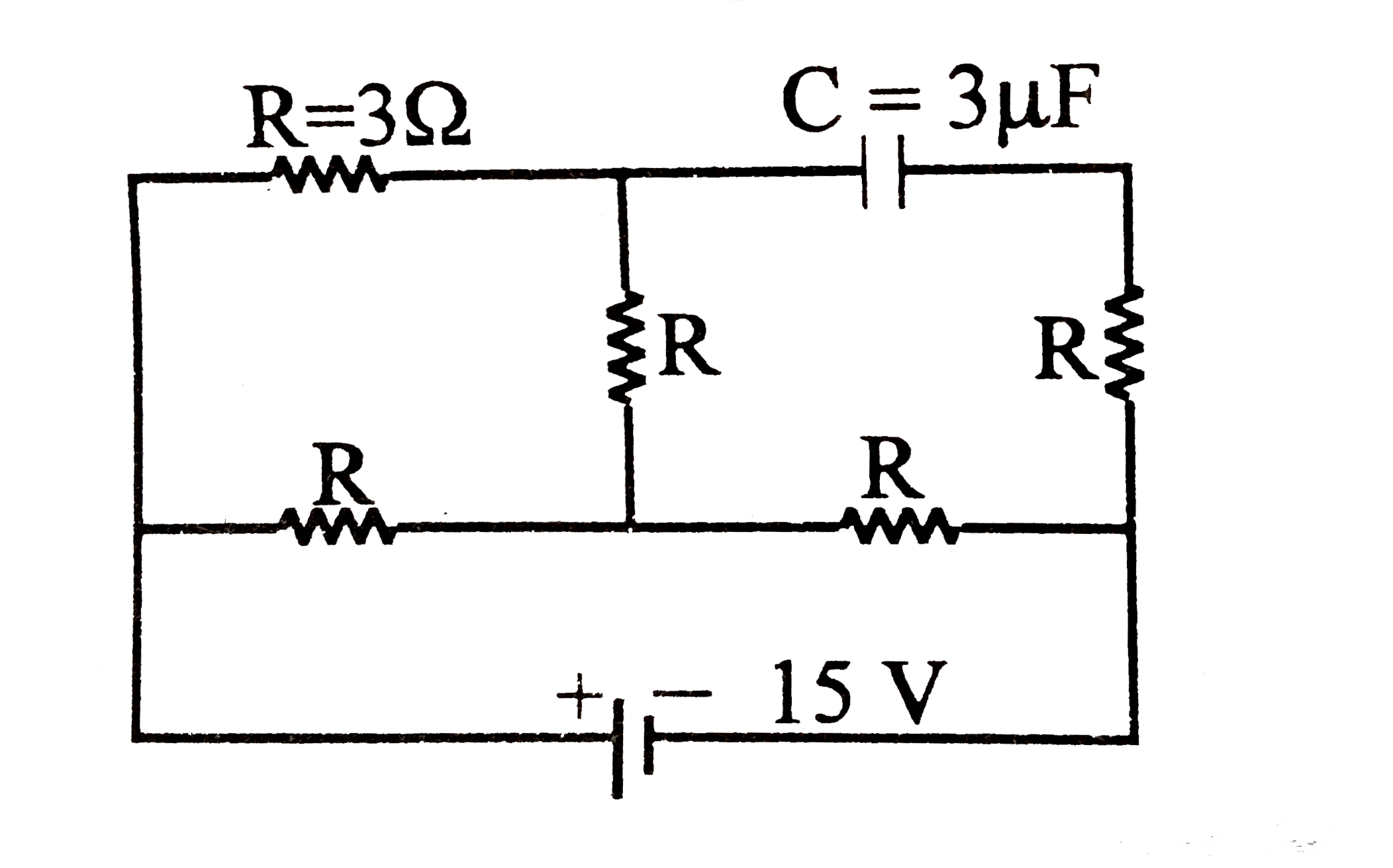
View SolutionIn the circuit shown, the cell is ideal , with emf=15V. Ecah resistance is of 3Ω. the potential difference across the capacitor is
View Solution
