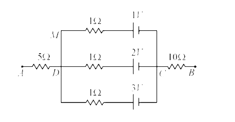
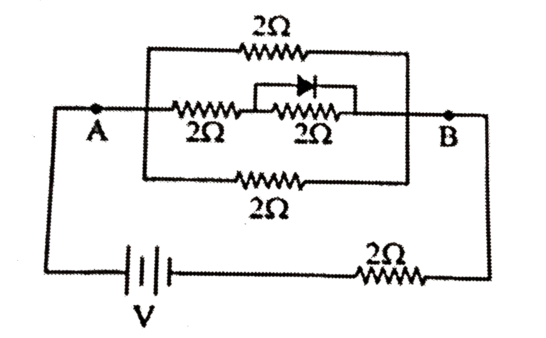
In the circuit shown in fig. some potential difference is applied between A and B. The equivalent resistance between A and B is R.

No current flows through the 5−Ω resistor
R=15Ω
R=12.5Ω
R=185Ω
The correct Answer is:A, D
Step by step video, text & image solution for In the circuit shown in fig. some potential difference is applied between A and B. The equivalent resistance between A and B is R. by Physics experts to help you in doubts & scoring excellent marks in Class 12 exams.
Updated on:21/07/2023Topper's Solved these Questions
Similar Questions
Knowledge Check
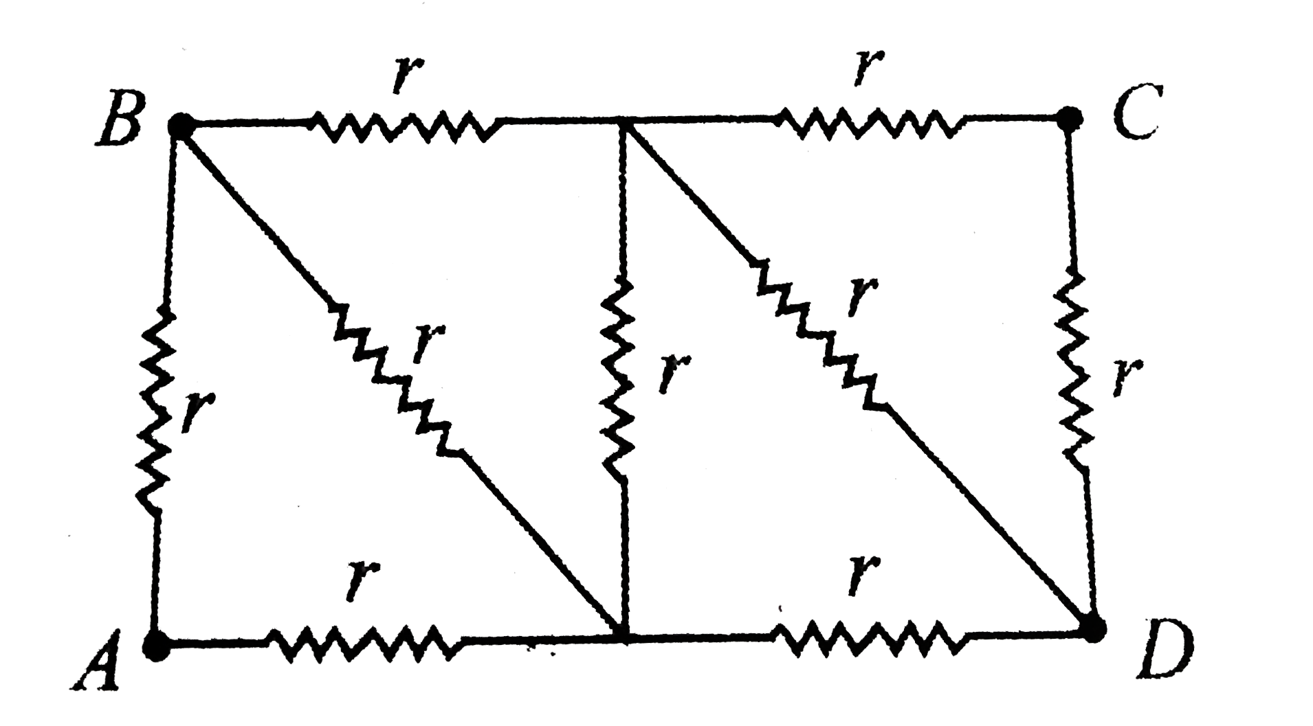
Equivalent resistance between A and B in Fig. is
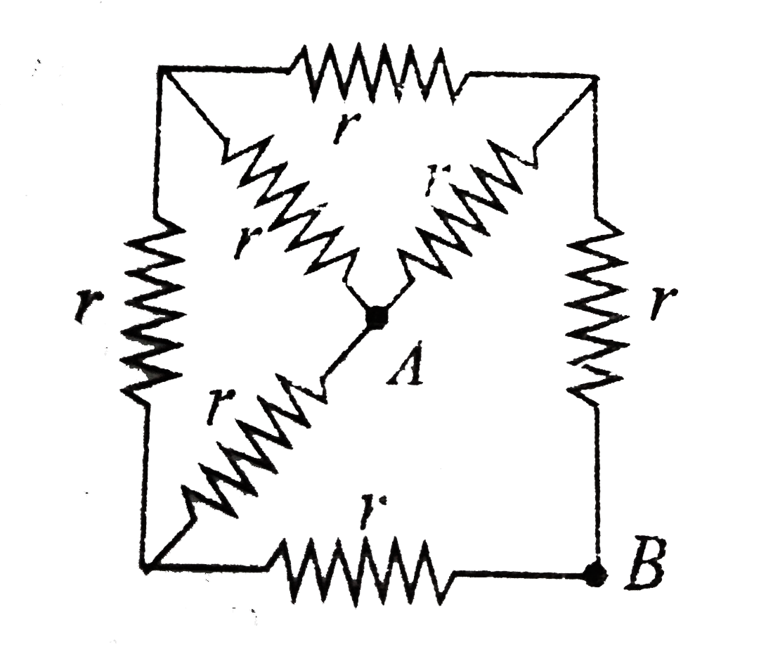 A8r/7B7r/8C3r/4Dr
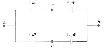
In the circuit shown, some potential difference is applied between A and B If C is joined to D
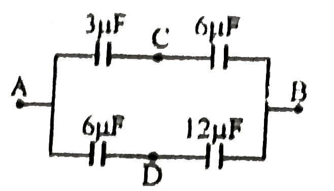 Ano charge will flow between C and DBsome charge will flow between C and DCthe equivalent capacitance between A and B will not changeDthe equivalent capacitance between A and B will change.
In the circuit shown in figure potential difference between A and B is
 A30 VB60 VC10 VD90 V
In the circuit shown in the following figure some potential difference is applied between A and B . IF C is joined to D,
View SolutionFor the circuit shown in fig. the equivalent resistance between A and C is
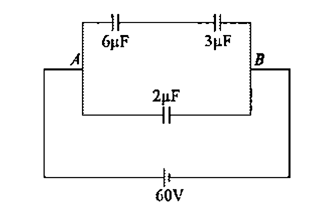
View SolutionIn the circuit shown, the potential difference across the 3μF capacitor is V and the equivalent capacitance between A and B is C Then:
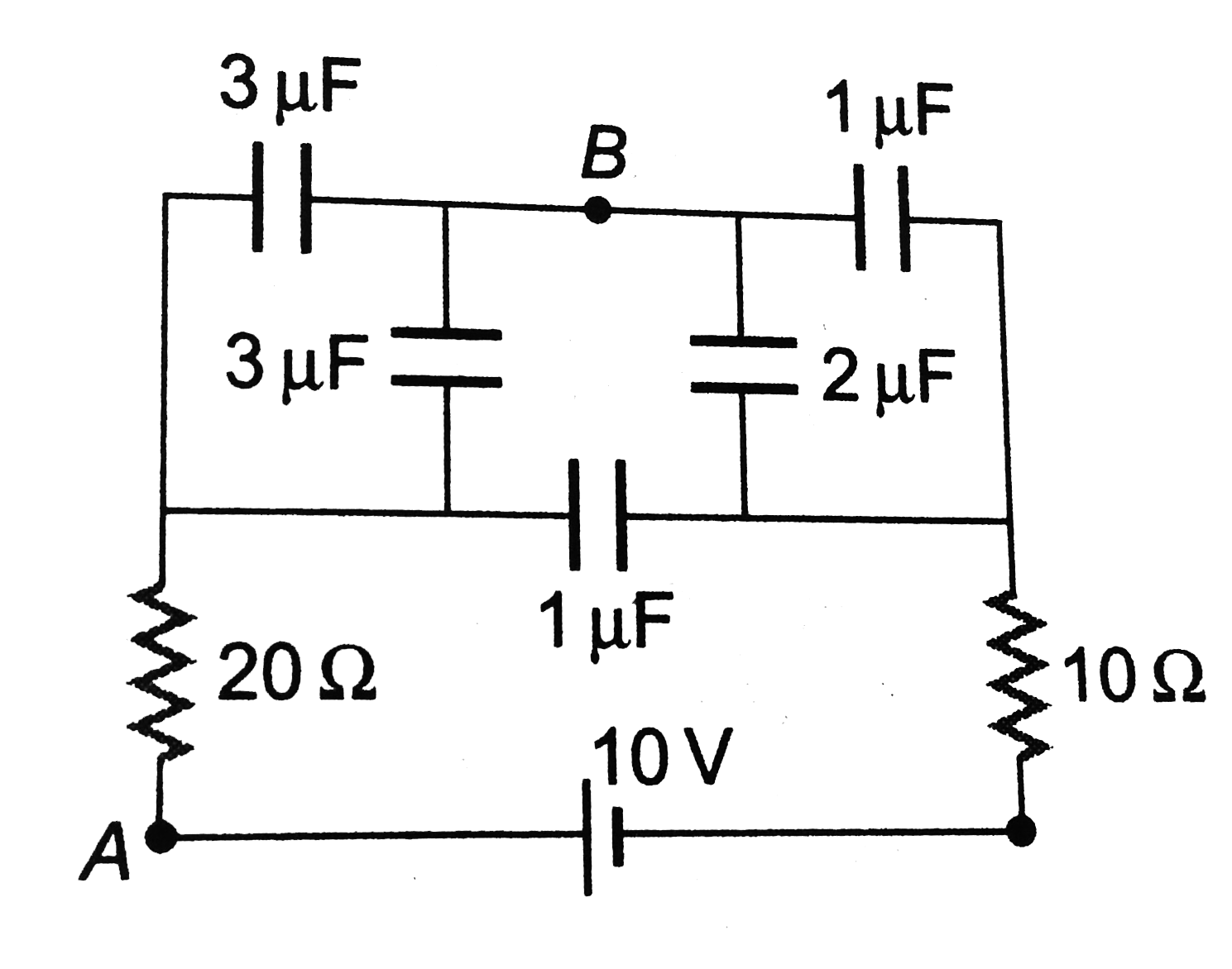
View SolutionIn the circuit shown in figure potential difference between the points A and B in the steady state is
View SolutionIn the circuit shown in figure , the diode is ideal The potential difference between A and B is
View Solution


