In the circuit shown in fig. the cell has emf 10V and internal resistance 1Ω
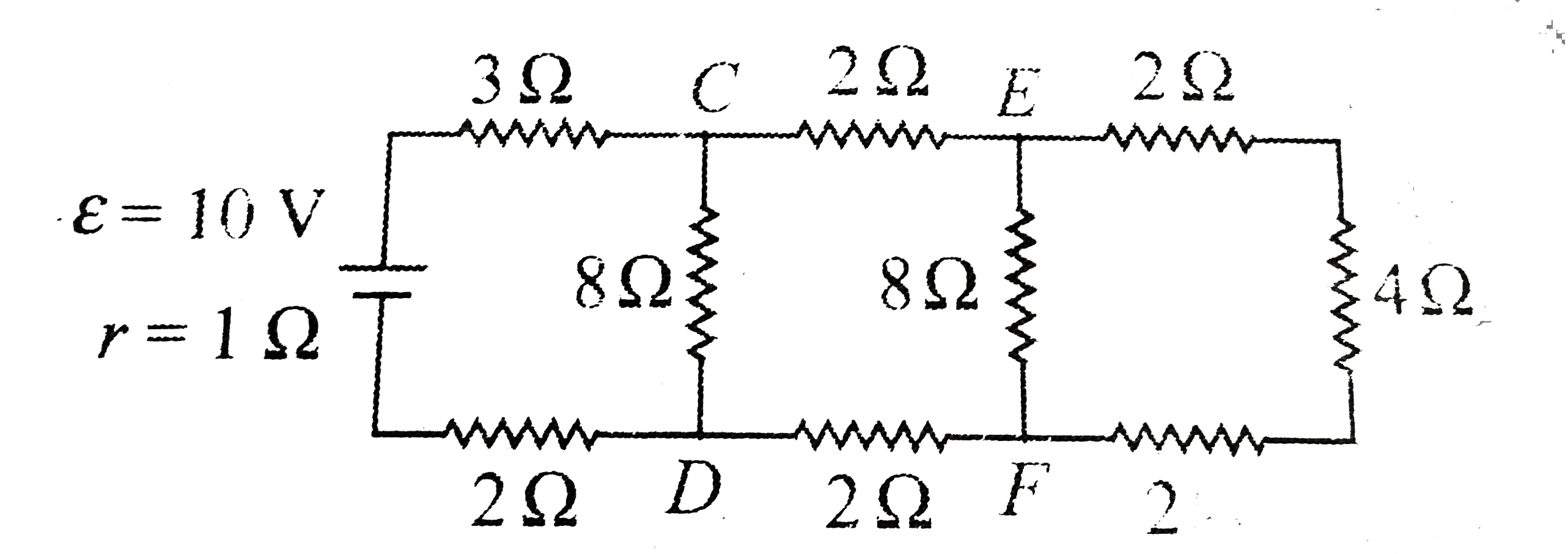
The current through the 3−Ωs resistor is 1A.
The current though the 3−Q resistor is 0.5A
The current through the 4−Ω resistor is 0.5A
The current through the 4−Ω resistor is 0.25A
The correct Answer is:A, D
Step by step video, text & image solution for In the circuit shown in fig. the cell has emf 10V and internal resistance 1 Omega by Physics experts to help you in doubts & scoring excellent marks in Class 12 exams.
Updated on:21/07/2023Topper's Solved these Questions
Similar Questions
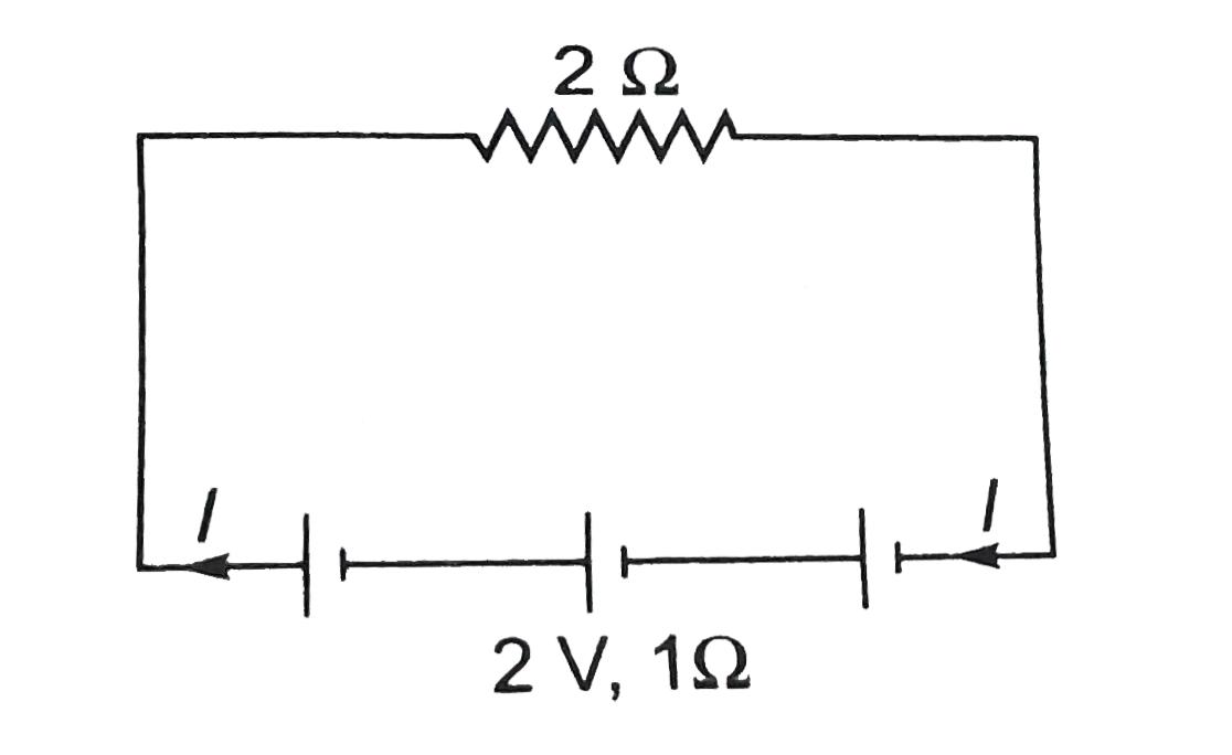
In the electric circuit shown each cell has an emf of 2 V and internal resistance of 1Ω. The external resistance is 2Ω . The value of the current is (in A)
View Solution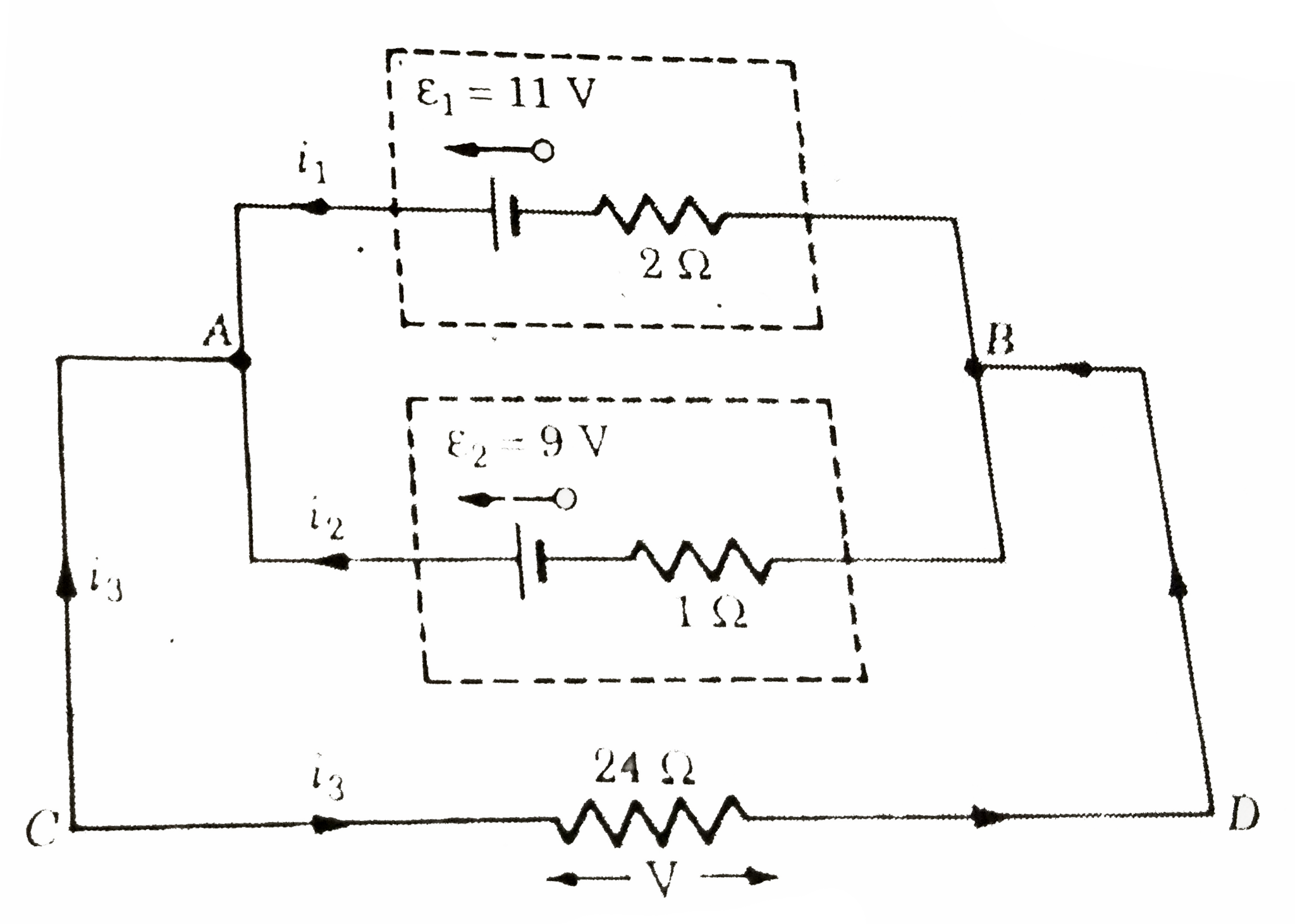
Compute the values of i1,i2,i3andV in the circuit, shown in figure. The emf and the internal resistance of the upper cell are 11V and 2Ω, and of the lower cell are 9 V and 1Ω.
View Solution
Knowledge Check
In the circuit shown below, the cell has an e.m.f. of 10V and internal resistance of 1ohm. The other resistances are shown in the figure. The potential difference VA−VB is
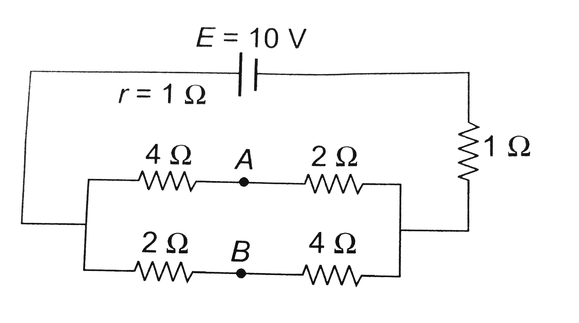 A6VB4VC2VD−2V
Three cells are connected to an external resistance as shown in the figure. Each of the cells has emf 10 V and internal resistance 2Ω.
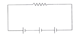
If the external resistance is 6Ω. Find the current in the circuit.A2AB2.5 AC3AD3.5 ATwo cells e1ande2 connected in opposition to each other as shown in figure. The cell of emf 9 V and internal resistance 3Ω the cell is of emf 7V and internal resistance 7Ω. The potential difference between the points A and B is
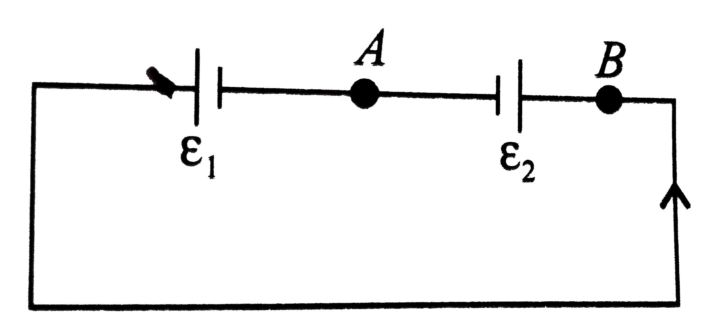 A8.4VB5.6VC7.8VD6.6V
An ammeter of resistance 0.02 Ω is connected in the usual may to a circuit in a circuit consisting of a cell of emf 2V and internal resistance 1Ω and a resistor of 9Ω. What is the percentage error in the reading of the ammeter?
[Hint: Ireal=210=0.2, Iapparent=210.02)
View SolutionIn the shown circuit the following battery is of emf 4V and internal resistance 8Ω. Find the potential difference between points x and y as shown in the circuit.

View SolutionIn the circuit shown in fig. the cell is ideal with emf 15V. Each resistance is of 3Ω. The potential difference across the capacitoro in steady state is
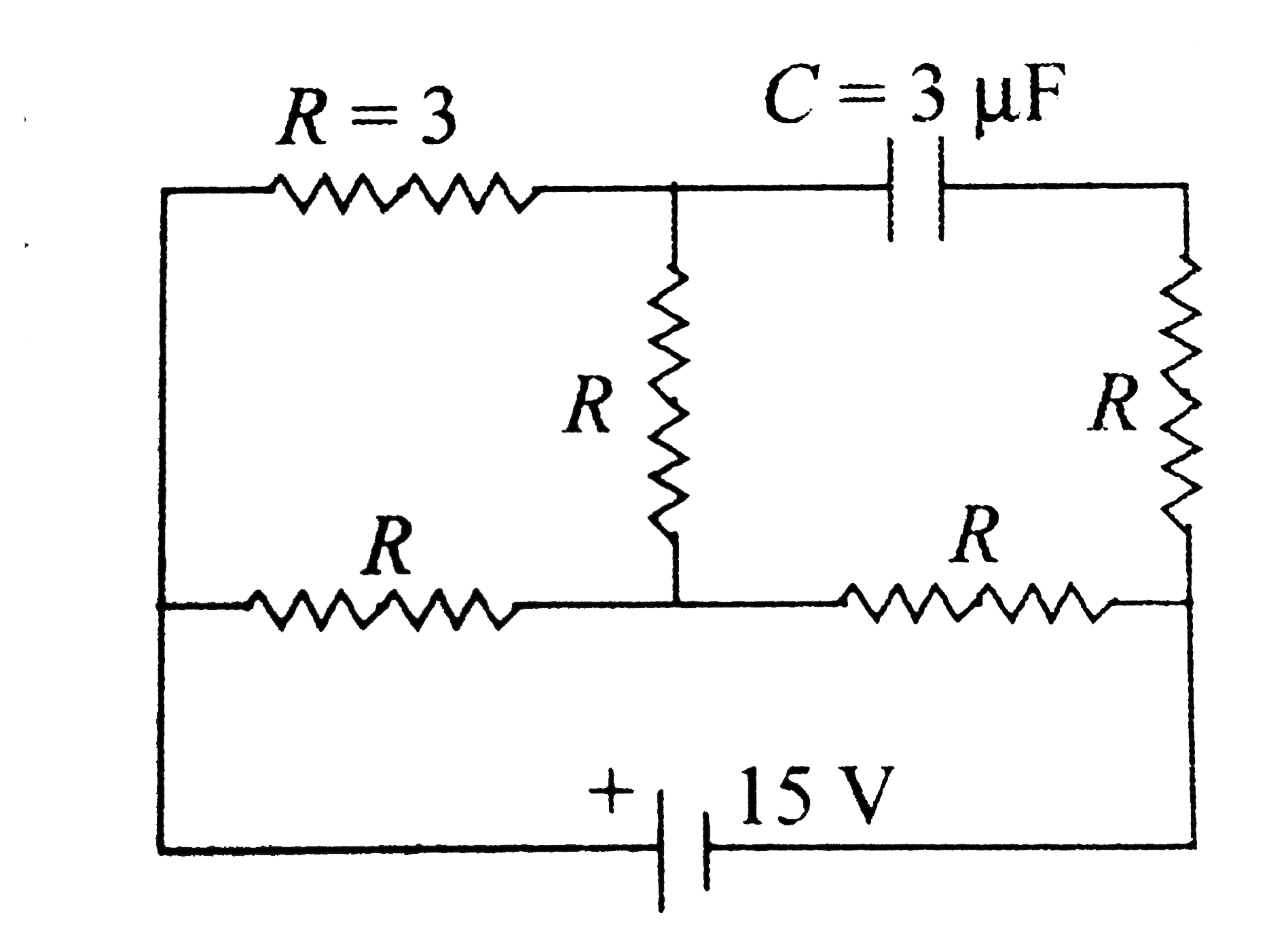
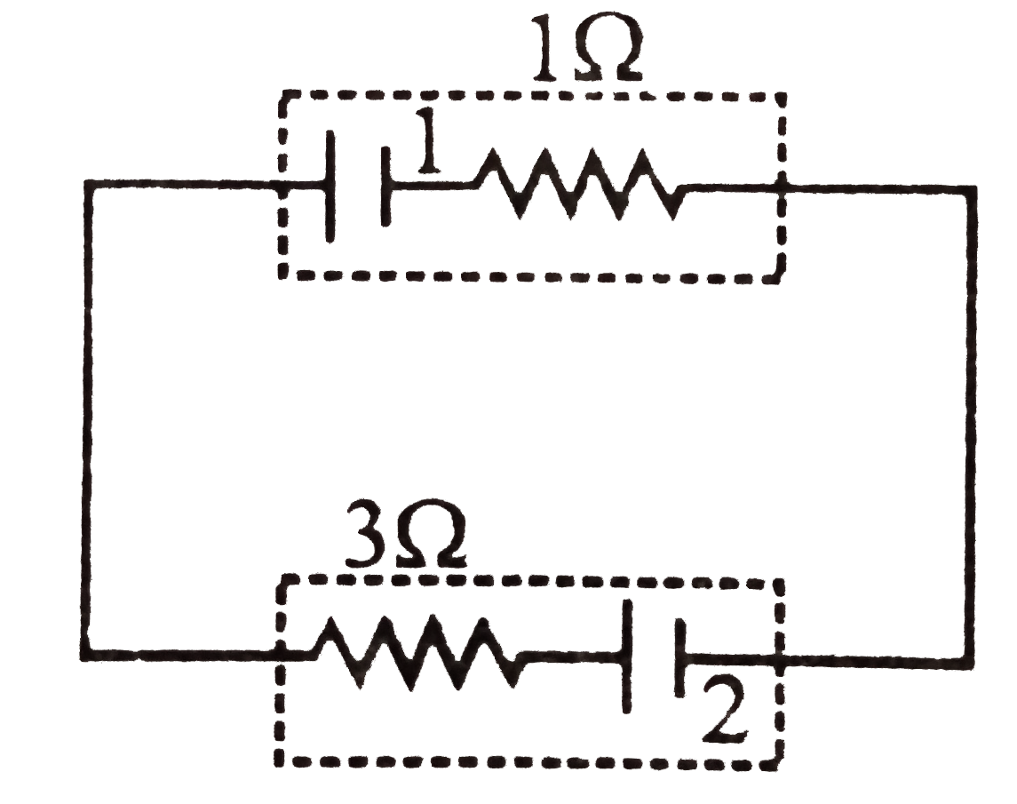
View SolutionIn the figure shown, battery 1 has emf=6V and internal resistance =1Ω. Battery 2 has emf=2V and internal resistance =3Ω. The wires have negligible resistance. What is the potential difference across the teminals of battery 2?
View Solution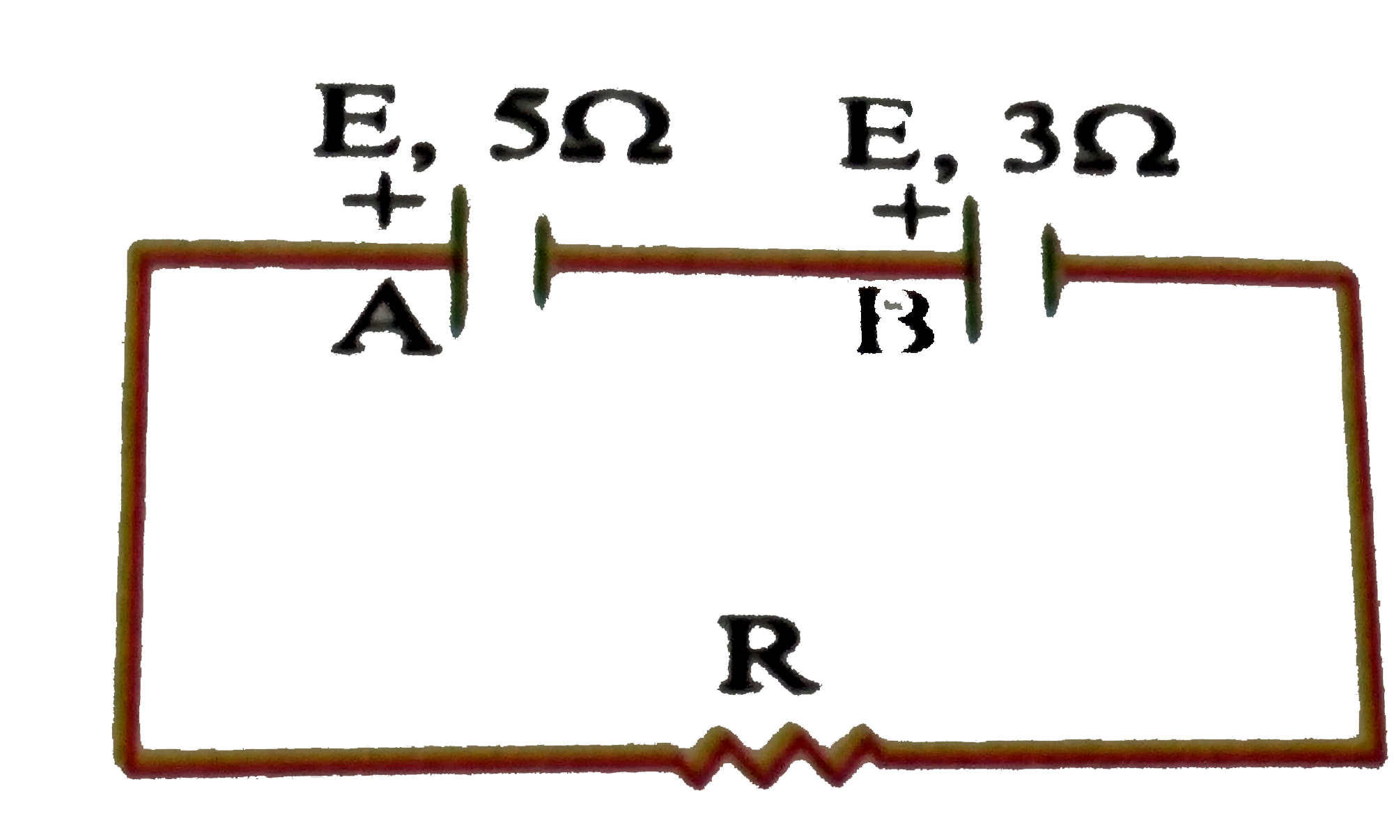
In the circuit shown here, cells A and B have emf 10 V each and the internal resistance is 5Ω for A and 3Ω for B. For what value of R will the potential difference across thhe cell A will be zero?
View Solution

