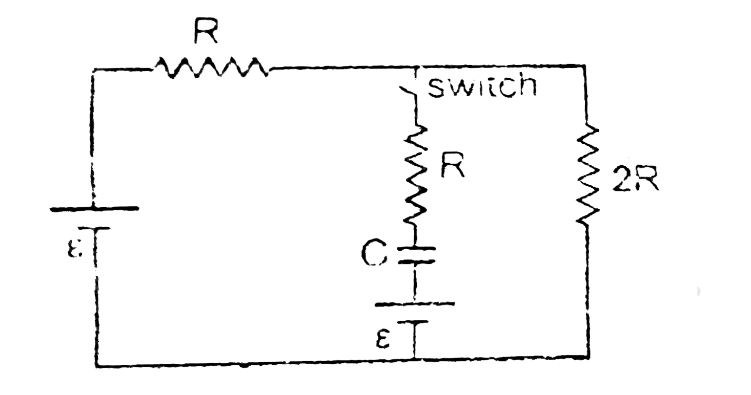
Initially the capacitor was uncharged Current in the capacitor just after switching on will be ?
εR
ε2R
ε5R
ε4R
The correct Answer is:C
Just after switching the capacitor will act like a conducting wire. So effective circuit will be
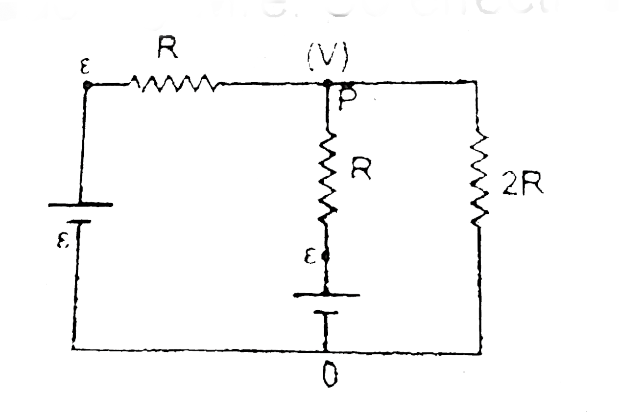
By applying KVL at point PV−εR+V−εR+V2R=0
V=4ε5
So, current in the branch containing capacitor =ε5R
Topper's Solved these Questions
- DAILY PRACTICE PROBLEMBook:RESONANCEChapter:DAILY PRACTICE PROBLEMExercise:DPP No.48
Explore 9 Videos
- DAILY PRACTICE PROBLEMBook:RESONANCEChapter:DAILY PRACTICE PROBLEMExercise:DPP No.49
Explore 20 Videos
- DAILY PRACTICE PROBLEMBook:RESONANCEChapter:DAILY PRACTICE PROBLEMExercise:DPP No.46
Explore 11 Videos
- CURRENT ELECTRICITYBook:RESONANCEChapter:CURRENT ELECTRICITYExercise:High Level Problems (HIP)
Explore 21 Videos
- ELECTRO MAGNETIC WAVESBook:RESONANCEChapter:ELECTRO MAGNETIC WAVESExercise:Exercise 3
Explore 27 Videos
Similar Questions
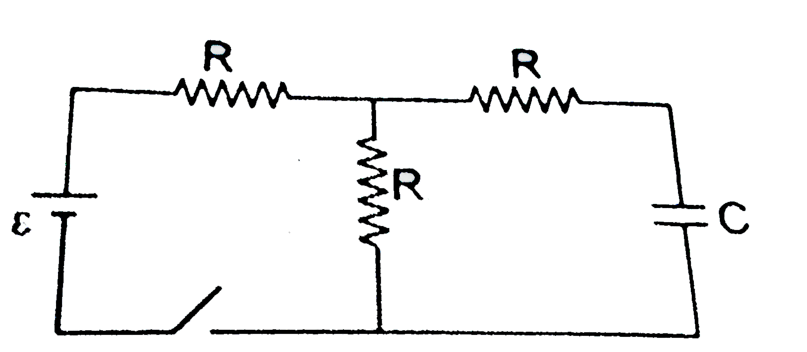
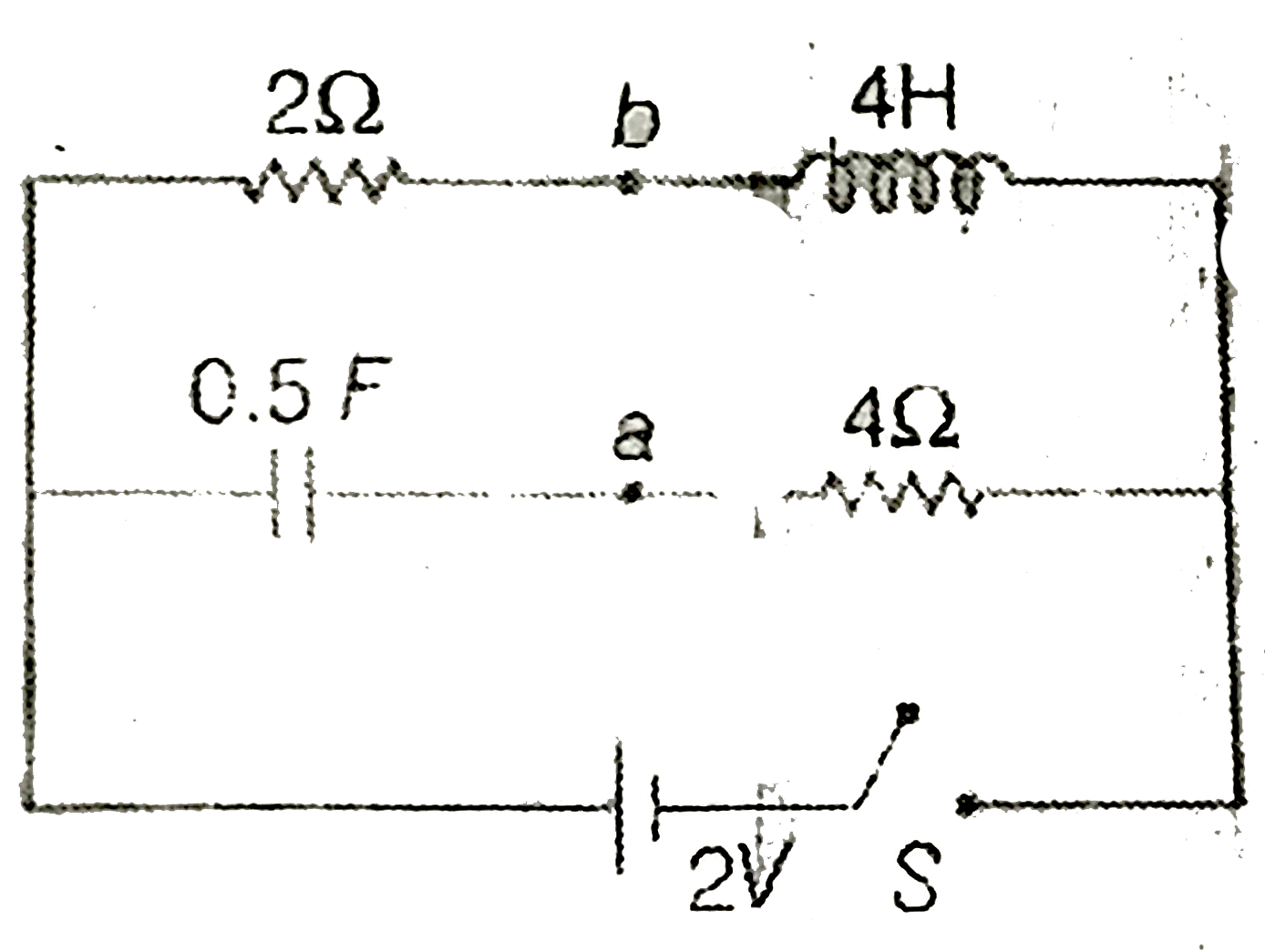
Initially the capacitor is uncharged find the charge on capacitor as a function of time, if switch is closed at t=0.
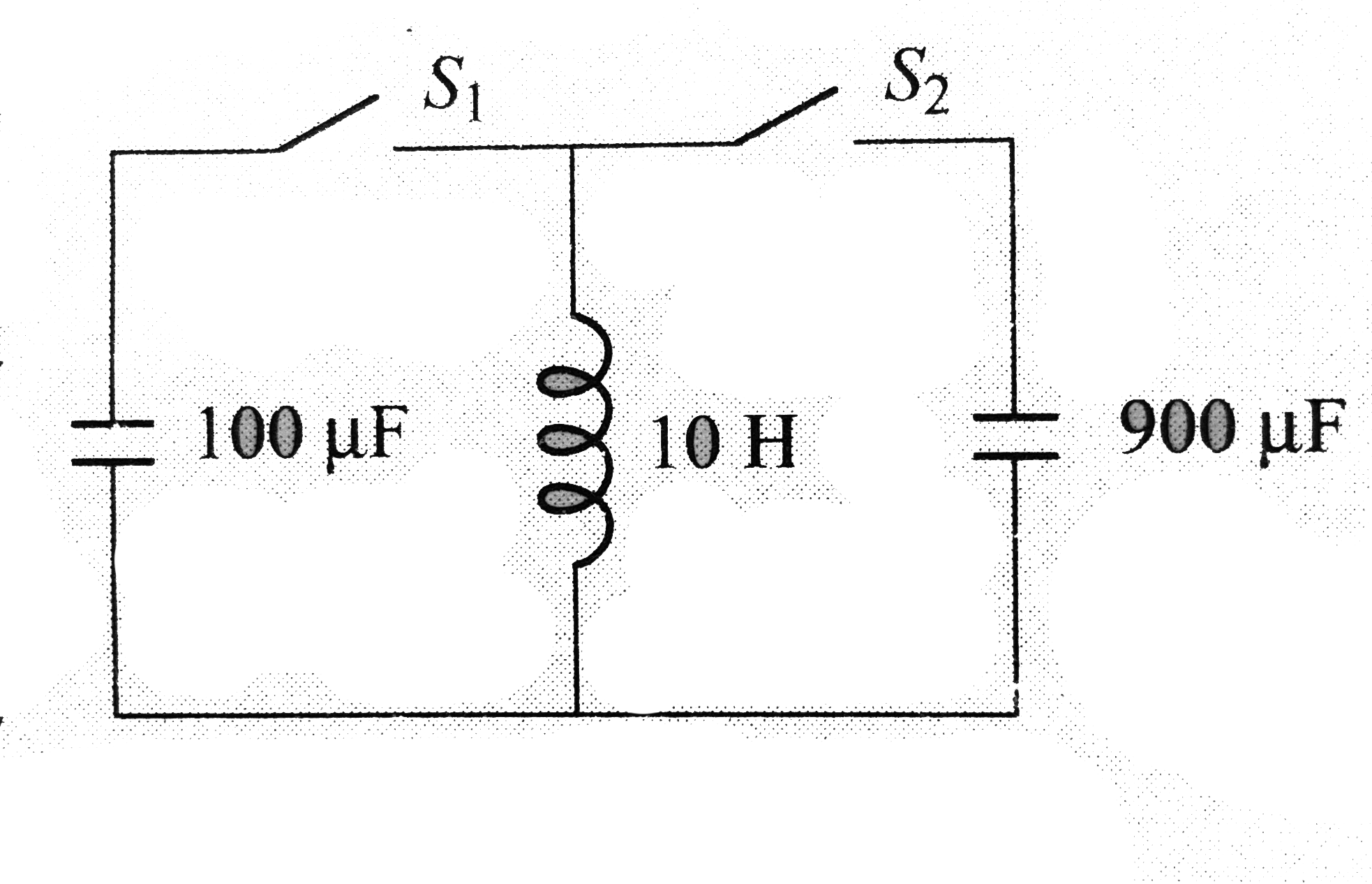
View SolutionInitially the 900μF capacitor is charged to 100V and the 100μFcapacitor is uncharged in Fig. Then switch S2 is closed for time t1, after which it is opened and at the same instant switch S1 is closed for time t2 and then opened. It is now found that 100μF capacitor is charged to 300μF capacitor is charged to 300V. Find the minimum possible value of the time interval t1 and t2.
View Solution
Knowledge Check
In the given figure switch is open initially and capacitor C2 is unchanged
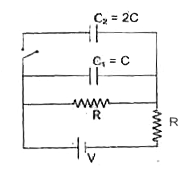
Charge on C2 just after closing the switch isACV2BCV3CCV4DCV8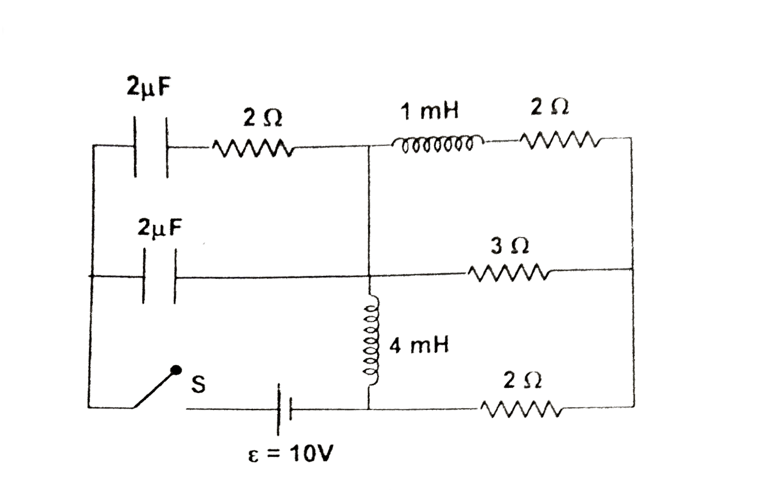
In the circuit shown, all the capacitors are initially uncharged. The current through the battery just after closing the switch 'S' isA2AB4AC5AD10AIn the given figure switch is open initially and capacitor C2 is unchanged
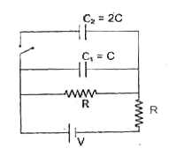
Potential difference on C1just after closing the switch isAV3BV6CV4DV2
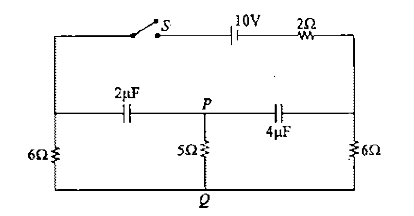
In the circuit shown in figure-3.351 the capacitors are initially uncharged. The current through resistor PQ just after closing the switch is :
View SolutionIn the circuit shown. Initially the capacitor is uncharged. The switch S is closed at time t=0. Then
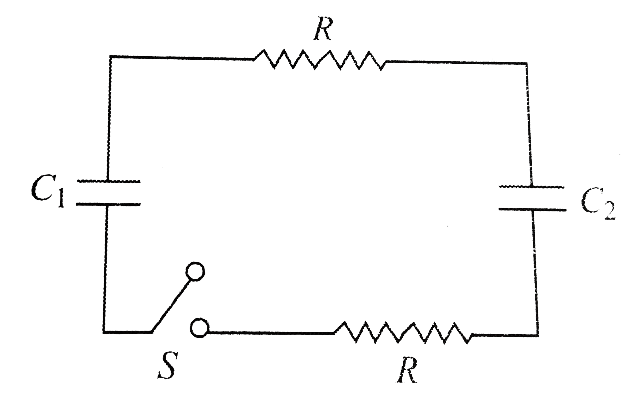
View SolutionIn the circuit shown in fig. C1=2C2 Initially, capacitor C1 is charged to a potential of V. The current in the circuit just after the switch S is closed is
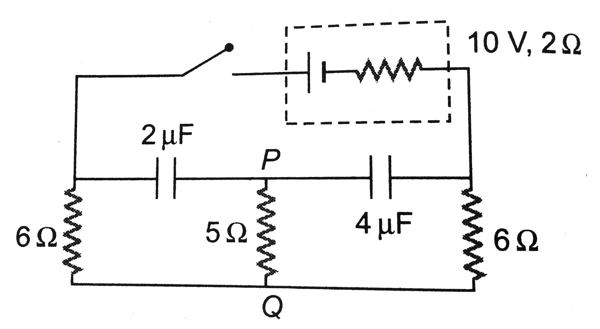
View SolutionIn the circuit shown in figure, the capacitors are initially uncharged. The current through resistor PQ just after closing the switch is
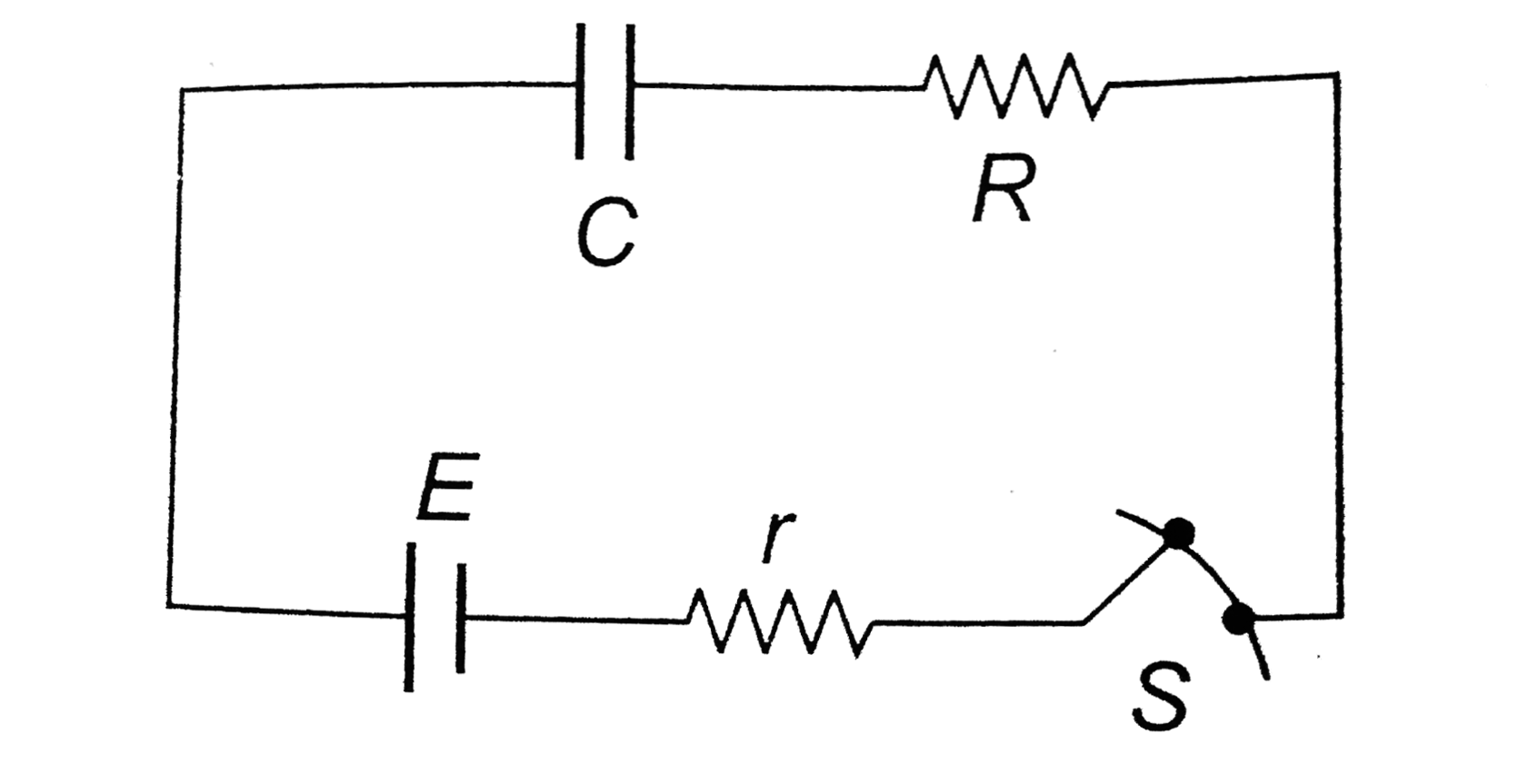
View SolutionAssertion : The switch S shown in the figure is closed at t=0. Initial current flowing through battery is ER+r
Reason : Initially capacitor was uncharged, so resistance offered by capacitor at t=0 is zero
View Solution

