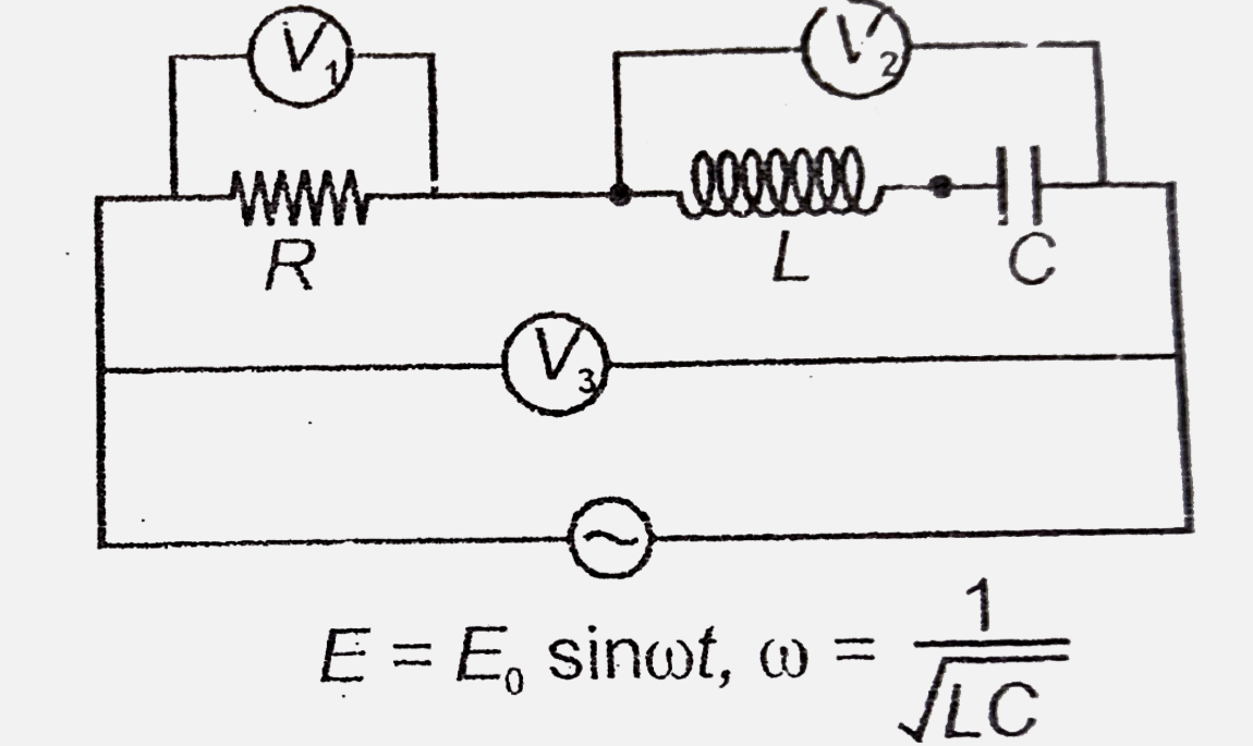
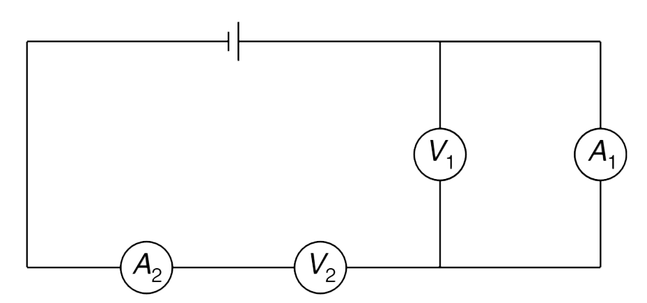
Consider the circuit shown in the figure, the cell is ideal. The readings of the ideal voltmeters V1 and V2 in volts are respectively.

A
2,0
B
0,2
C
0,0
D
2,2
Video Solution
Text Solution
The correct Answer is:B
Since current through cell is negligible the potential difference across 5 ohm resistor tends to zero, and the potential difference across V2 will be 5V.
|
Topper's Solved these Questions
- DAILY PRACTICE PROBLEMBook:RESONANCEChapter:DAILY PRACTICE PROBLEMExercise:DPP No.48
Explore 9 Videos
- DAILY PRACTICE PROBLEMBook:RESONANCEChapter:DAILY PRACTICE PROBLEMExercise:DPP No.49
Explore 20 Videos
- DAILY PRACTICE PROBLEMBook:RESONANCEChapter:DAILY PRACTICE PROBLEMExercise:DPP No.46
Explore 11 Videos
- CURRENT ELECTRICITYBook:RESONANCEChapter:CURRENT ELECTRICITYExercise:High Level Problems (HIP)
Explore 21 Videos
- ELECTRO MAGNETIC WAVESBook:RESONANCEChapter:ELECTRO MAGNETIC WAVESExercise:Exercise 3
Explore 27 Videos
Similar Questions
Knowledge Check
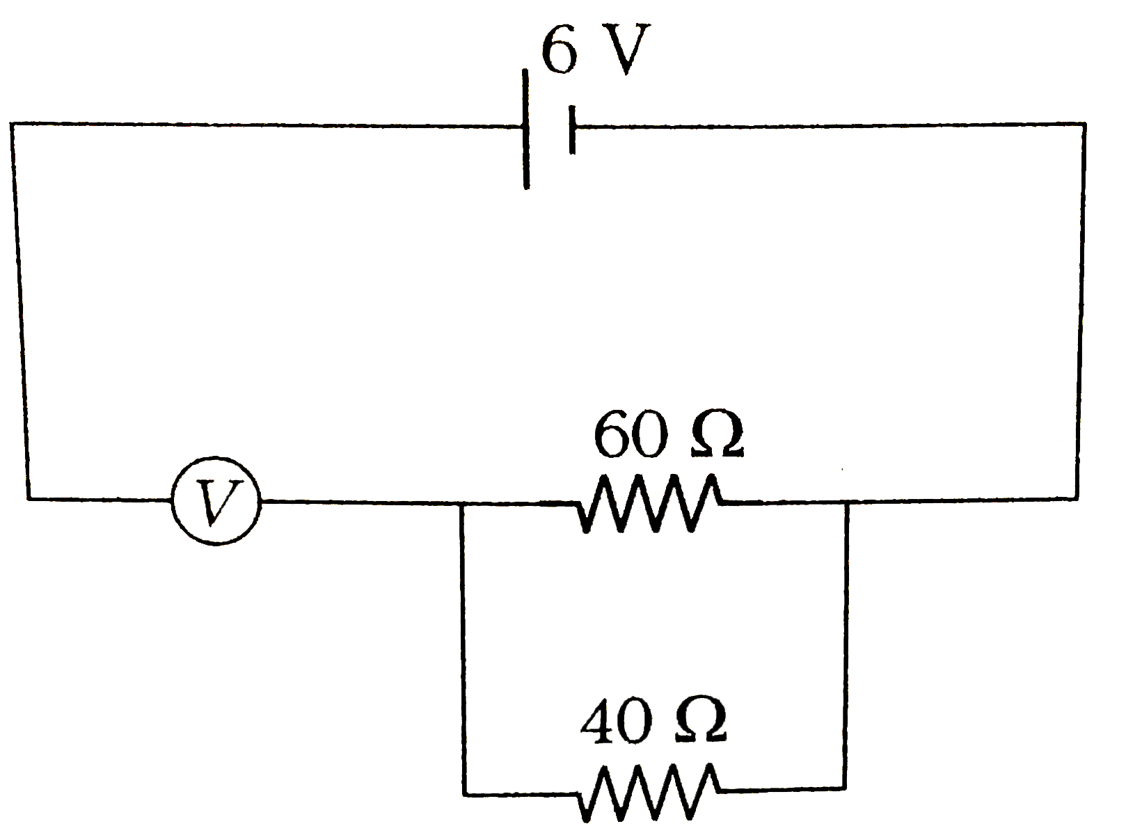
In the circuit shown in the figure, the voltmeter reading is
 A2.4VB3.4VC4.0VD6.0V
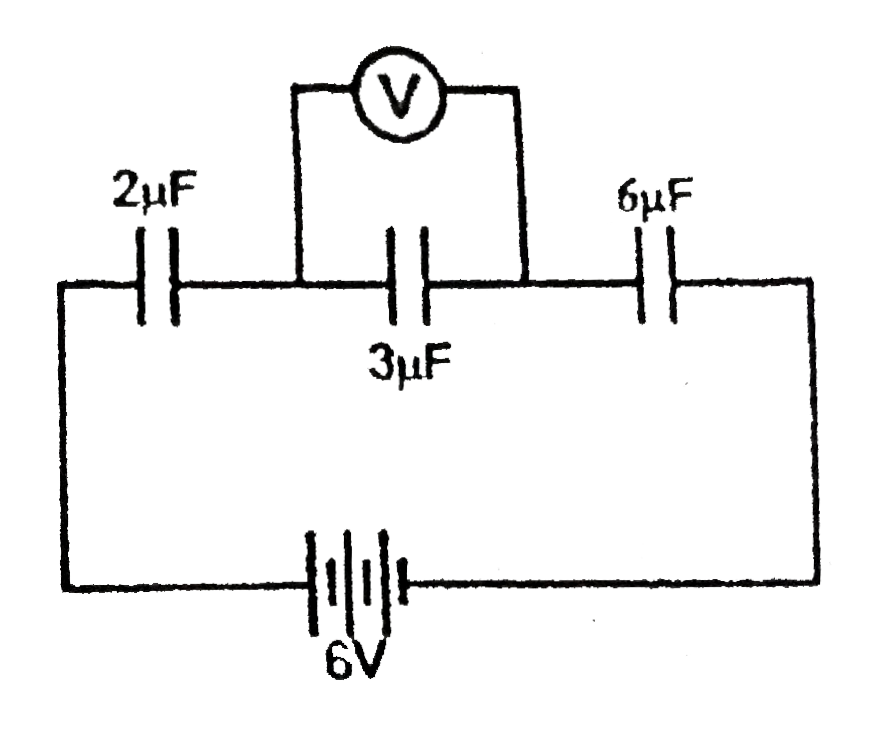
In the combination shown in the figure, the ideal voltmeter reading will be
 A4.5 VB(1811)VC3VD2V
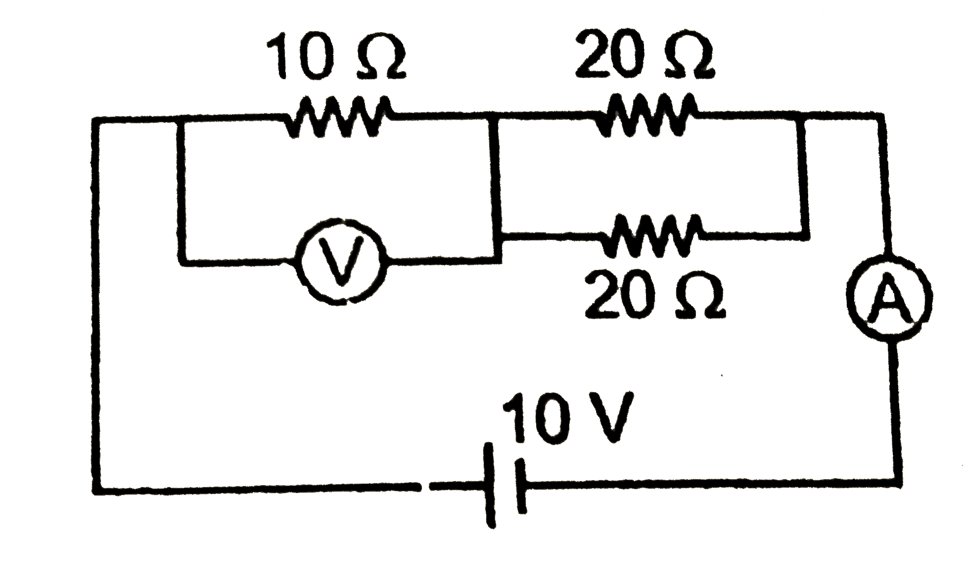
A circuit is shown in the figure. The ratio of readings of ideal voltmeter to reading of ideal ammeter is
 A5B0.5C10D2.5
In the series LCR circuit as shown in the figure, the voltmeter V and ammeter A reading are
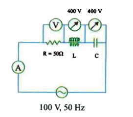
View SolutionIn the series LCR circuit as shown in the figure, the voltmeter V and ammeter A reading are

View SolutionIn the circuit shown in figure the voltmeters V1&V2 are identical. If readings of ammeter A2, Voltmeter V2andV1 are 400μA,100Vand2V respectively, find the resistance of ammeter A1. Is the value realistic ?
View SolutionIn the series circuit shown in the figure the voltmeter reading will be (all the meters are ideal).
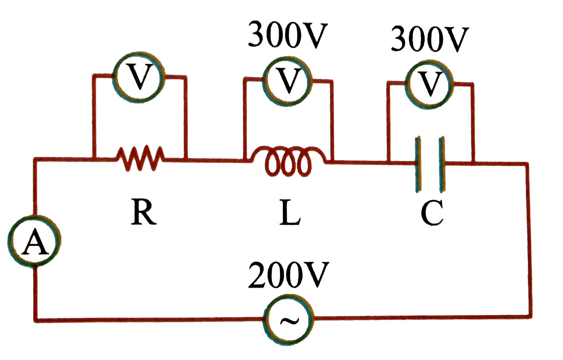
View SolutionIn the given circuit, the voltmeter and the electric cell are ideal. Find the reading of the voltmetre

View Solution


