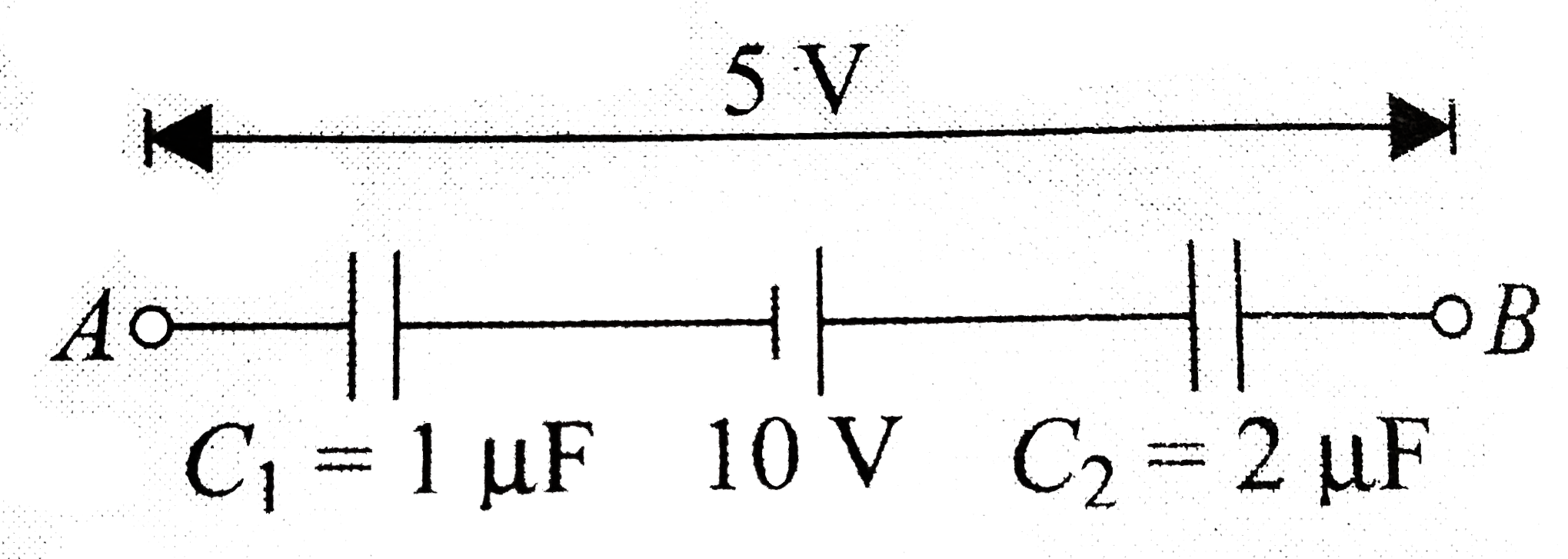
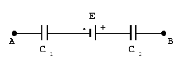
A circuit has a section Ab shown in fig. The emf of the source equals E=10V, the capacitances are equal to C1=1.0μF and C2=2.0μF, and the potential difference φA−φB=5.0V. Find the voltage across each capacitor.

10/3V,5/3V
10/3V,10/3V
5/2V,5/3V
0V,0V
The correct Answer is:A
Step by step video, text & image solution for A circuit has a section Ab shown in fig. The emf of the source equals E = 10V, the capacitances are equal to C_(1) = 1.0 muF and C_(2) = 2.0 muF, and the potential difference varphi_(A) - varphi_(B) = 5.0 V. Find the voltage across each capacitor. by Physics experts to help you in doubts & scoring excellent marks in Class 12 exams.
Updated on:21/07/2023Topper's Solved these Questions
- DAILY PRACTICE PROBLEMBOOK - RESONANCECHAPTER - DAILY PRACTICE PROBLEMEXERCISE - DPP No.41
9 Videos
- DAILY PRACTICE PROBLEMBOOK - RESONANCECHAPTER - DAILY PRACTICE PROBLEMEXERCISE - DPP No.42
20 Videos
- DAILY PRACTICE PROBLEMBOOK - RESONANCECHAPTER - DAILY PRACTICE PROBLEMEXERCISE - DPP No.39
9 Videos
- CURRENT ELECTRICITYBOOK - RESONANCECHAPTER - CURRENT ELECTRICITYEXERCISE - High Level Problems (HIP)
21 Videos
- ELECTRO MAGNETIC WAVESBOOK - RESONANCECHAPTER - ELECTRO MAGNETIC WAVESEXERCISE - Exercise 3
27 Videos
Similar Questions
A circuit has section AB as shown in figure. The emf of the source equals E=10V, the capacitor capacitances are equal to C1=1.0μF and C2=2.0μF, and the potential difference VA−VB=5.0V. Find the voltage across each capacitor.

View SolutionA circuit has section AB as shown in The emf of the cell is 10V, and the capacitors have capacitances C1=1μF and C2=2μF.
 .
.
View Solution
Knowledge Check
A circuit has a section AB as shown in the fig. With E =10V. C1=1.0μF,C2=2.0μF and the potential difference VA–VB=5V. The voltage across C1 is :
 AzeroB5VC10VD15V
For section AB of a circuit shown in , C1=1μF,C2=2μF,E=10V, and the potential difference VA−VB=−10V. Charge on capacitor C1 is
 . A0μCB20/3μCC40/3μCDnone of these
A circuit shown in the figure consists of a battery of emf 10V and two capacitance C1 and C2 of capacitances 1.0μF and 2.0μF respectively. The potential difference VA−VB is 5V
 ACharge on capacitor C1 is equal to charge on capacitor C2BVoltage across capacitor C1 is 5V.CVoltage across capacitor C2 is 10VDEnegry stored in capacitor C1 is two times the enegry stored in capacitor C2.
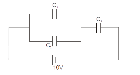
In the circuit shown the capacitors are C1=15μF,C2=10μFandC3=25μF. Find

the potential difference across each capacitor.
View SolutionIn the circuit shown in Fig. the emf of the sources is equal to ξ=5.0V and the resistances are equal to R1=4.0Ω and R2=6.0Ω. The internal resistance of the source equals R=1.10Ω. Find the currents flowing through the resistances R1 and R2.

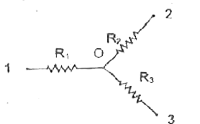
View SolutionFind the current flowing through the resistance R1 of the circuit shown in Fig. If the resistances are equal to R1=10Ω.R2=20Ω and R3=30Ω, and the potential of points 1,2 and 3 are equal to φ1=10V,φ2=6V, and φ3=5V

View SolutionFind the current flowing through the resistance R1 of the circuit shown in figure if the resistances are equal to R1=10Ω,R2=20ΩandR3,=30Ω and the potentials of the points 1, 2, and 3 are equal to φ1=10V,φ2=6Vandφ3=5V

View SolutionFind a potential difference φA−φB between the plates of a capacitor C in the circuit shown in Fig, if the sources have emf'sE1=40V,E2=1.0V and the resistances are equal to R1=10Ω,R2=20Ω, and R3=30Ω. The internal resistances of the sources are negligble.

View Solution
