The galvanometer shown in the figure reads 3A, while the ideal voltmeter reads 24 volt. The value of . The galvanometer resistance is :

The correct Answer is:C
or
or
Topper's Solved these Questions
- BOOK - RESONANCECHAPTER - DAILY PRACTICE PROBLEMEXERCISE - DPP No.419videos
DAILY PRACTICE PROBLEM
- BOOK - RESONANCECHAPTER - DAILY PRACTICE PROBLEMEXERCISE - DPP No.4220videos
DAILY PRACTICE PROBLEM
- BOOK - RESONANCECHAPTER - DAILY PRACTICE PROBLEMEXERCISE - DPP No.399videos
DAILY PRACTICE PROBLEM
- BOOK - RESONANCECHAPTER - CURRENT ELECTRICITYEXERCISE - High Level Problems (HIP)21videos
CURRENT ELECTRICITY
- BOOK - RESONANCECHAPTER - ELECTRO MAGNETIC WAVESEXERCISE - Exercise 327videos
ELECTRO MAGNETIC WAVES
Similar Questions
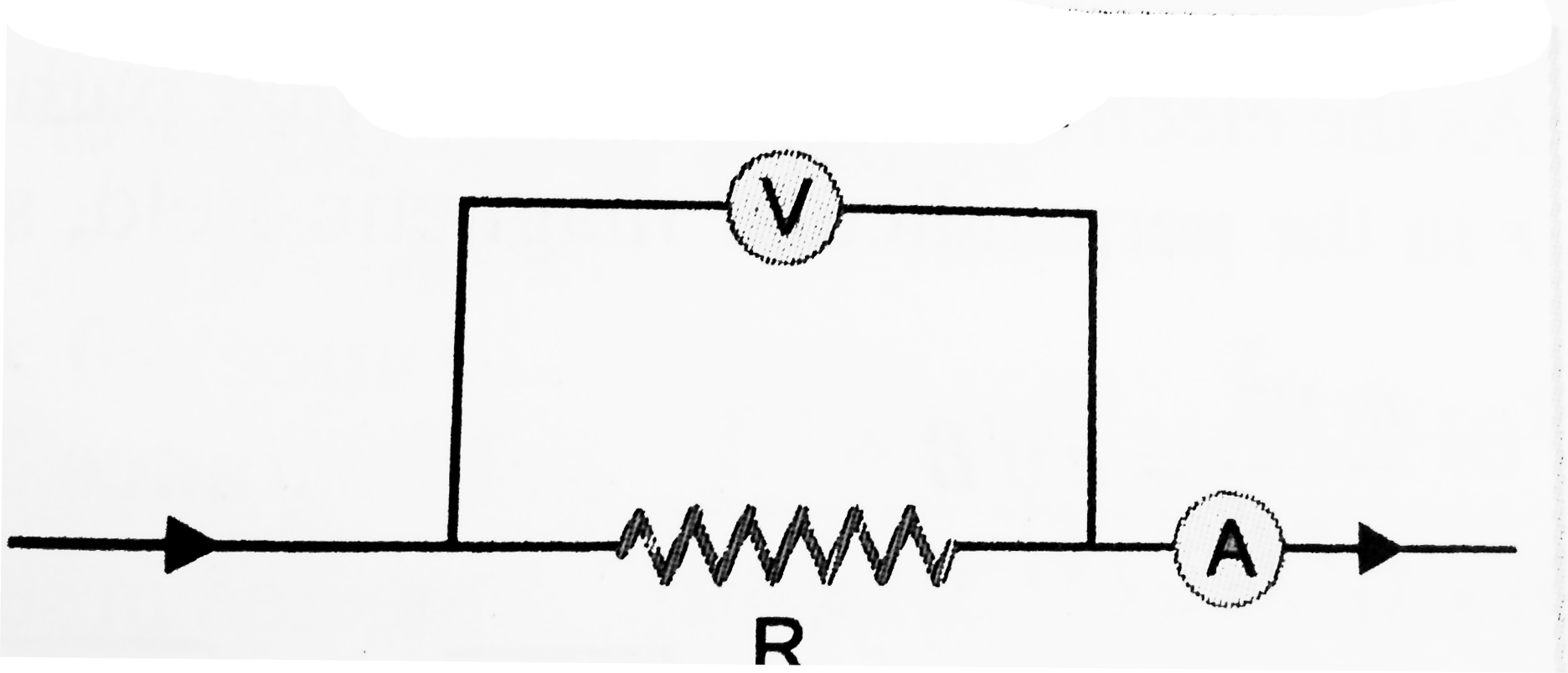
The voltmeter V in the figure. Reads 117V and the ammeter A reads 0⋅13A. The resistance of the voltmeter is 9000Ω and the resistance of ammeter is 0⋅015Ω. Compute (i) the resistance R, (ii) the power input to R.
 View Solution
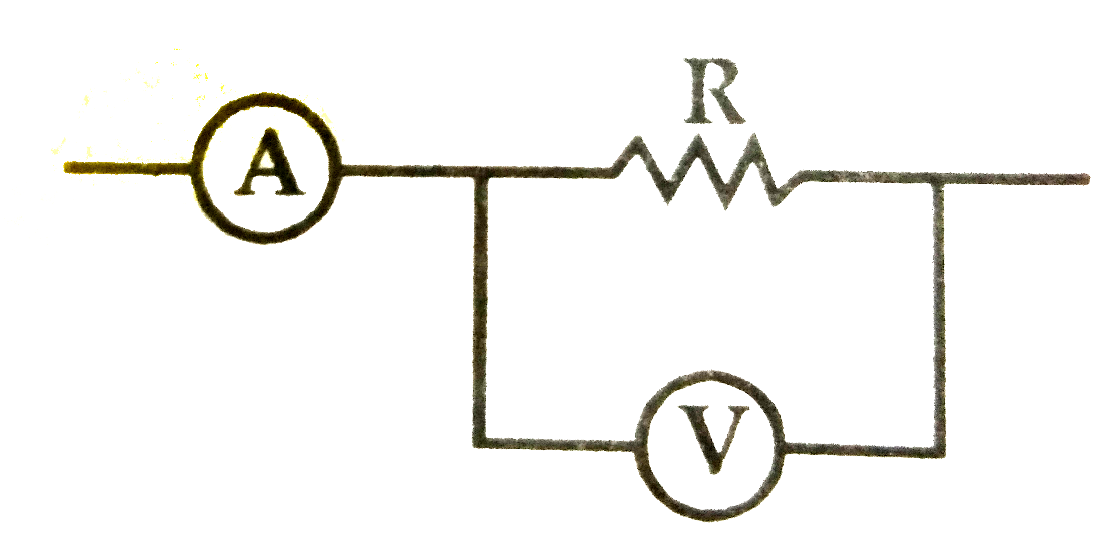
In given figure an ammeter reads 5 A and voltmeter reads 40 V. The actual value of resistance R is
 View Solution
Knowledge Check
- Question 1 - Select One
In the combination shown in the figure, the ideal voltmeter reading will be
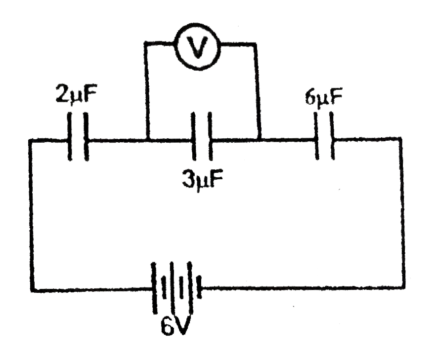 A4.5 VB(1811)VC3VD2V
 - Question 2 - Select One
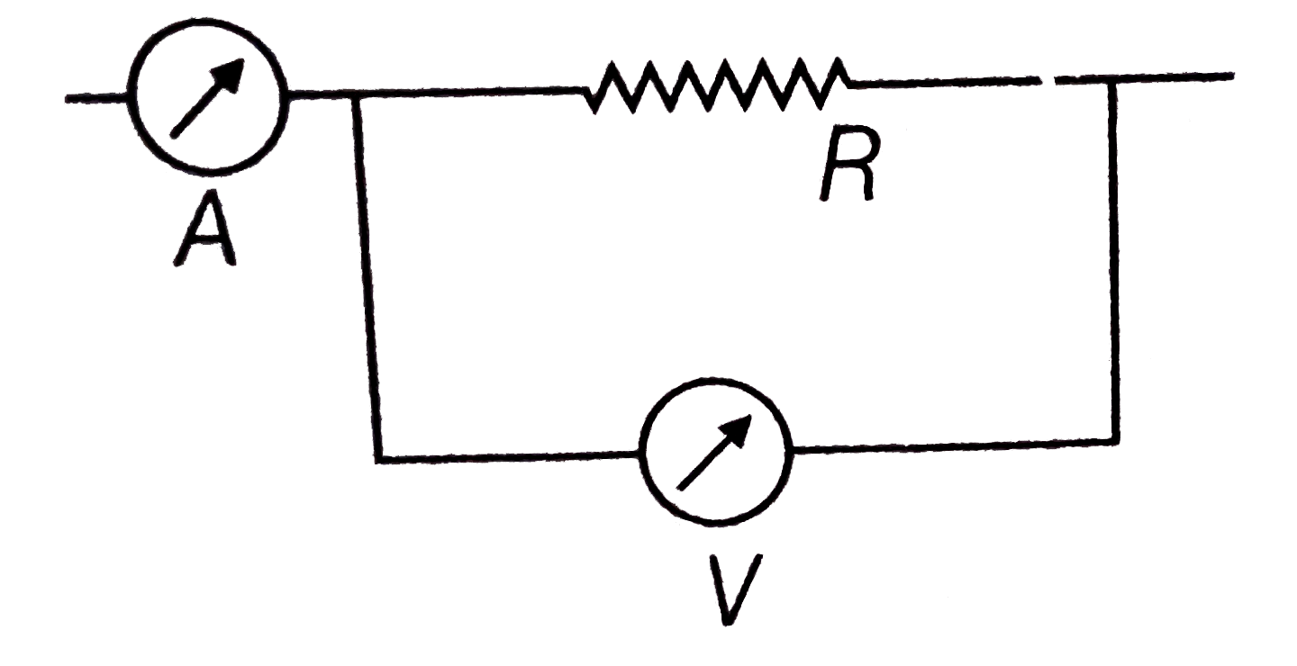
For the adjoining circuit diagram, the readings of ammeter and voltmeter are 2A and 120 V respectively. If the value of R is 75Ω, then the voltmeter resistance will be
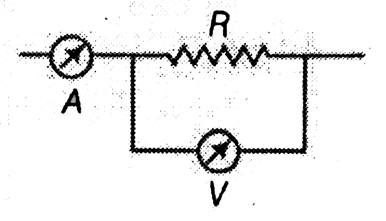 A100ΩB150ΩC300ΩD75Ω
 - Question 3 - Select One
In the adjoining circuit diagram, the readings of ammeter and voltmeter are 2 A and 120 V, respectively. If the value of R is 75Ω, then the voltmeter resistance will be
 A100ΩB150ΩC300ΩD75Ω
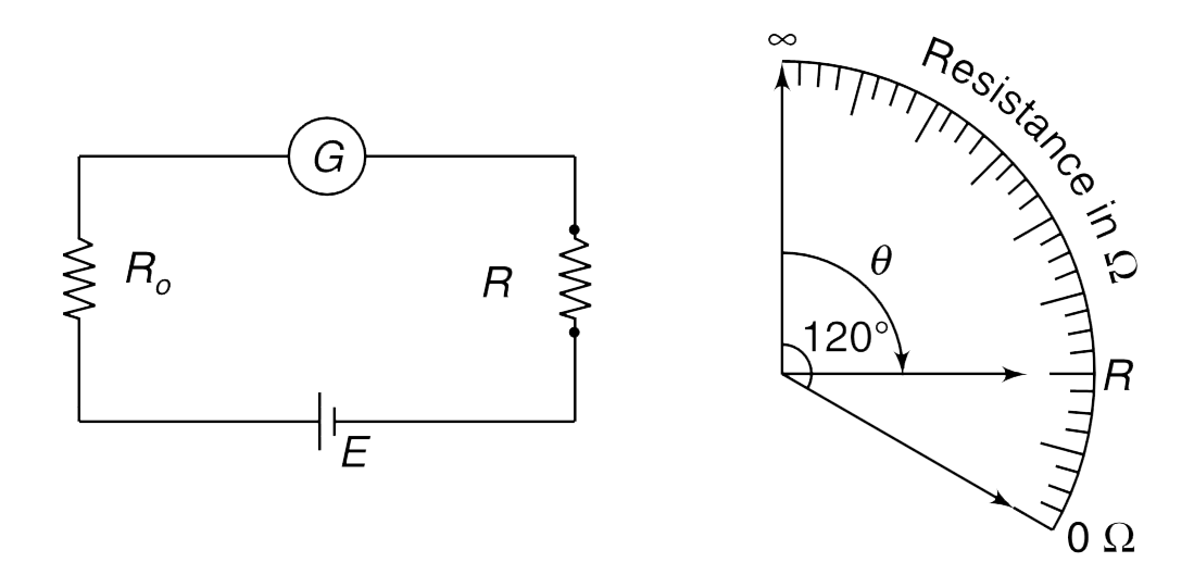
An ohm-meter is a device that measures an unknown resistance. A simple ohm-meter can be constructed using a galvanometer as shown in the figure. The cell used in the circuit has emf E=20 volt. The full scale deflection current and resistance of the galvanometer are 2mA and 20Ω respectively. R0 is a fixed resistance and R is the unknown resistance whose value is directly given by the galvanometer scale. The galvanometer scale is shown in figure. When an unknown resistance R is placed in the circuit, the pointer deflects by θ=90∘. Find R.
 View Solution
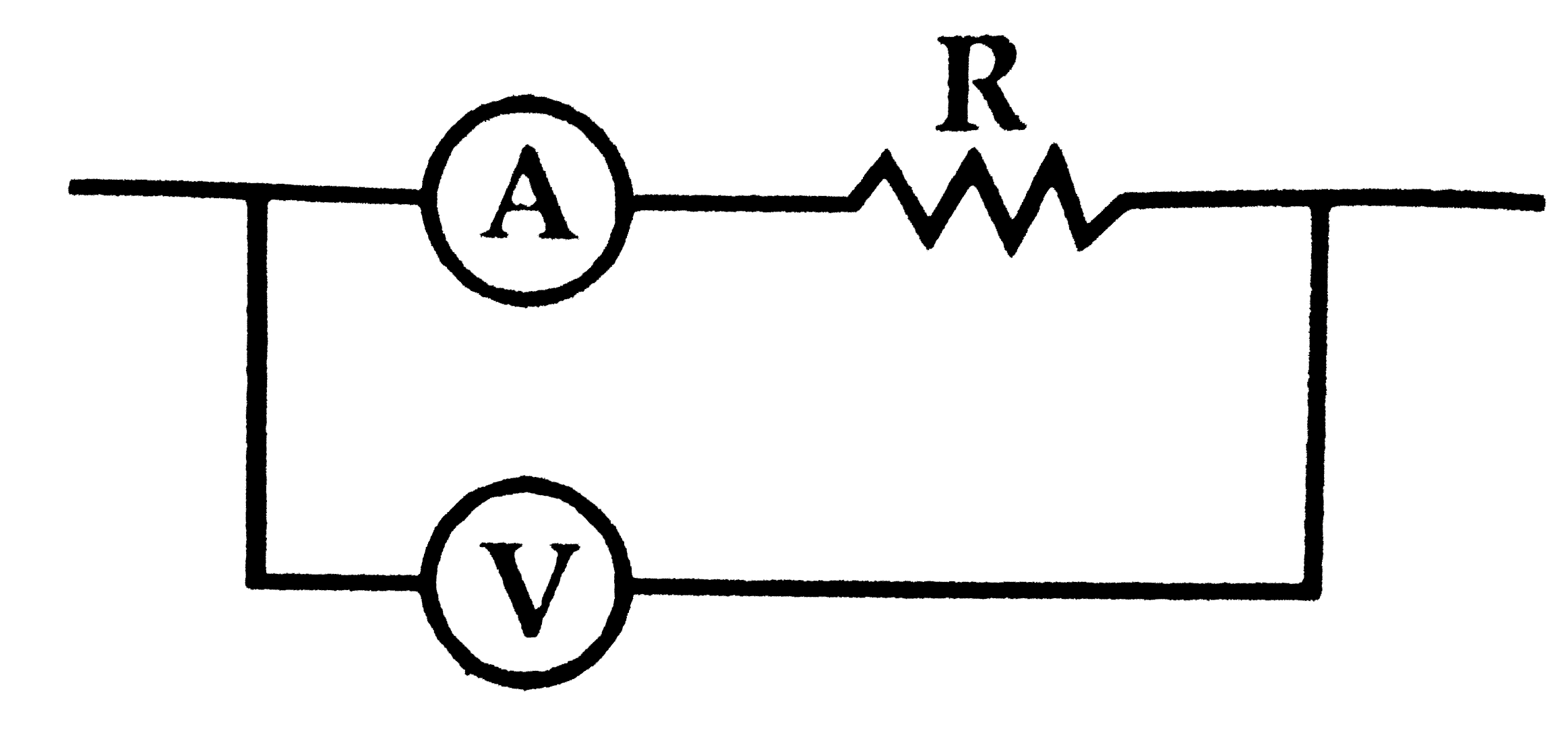
In given figure the ammeter A reads 5 A and voltmeter V reads 40 V. The actual value of resistance R is
 View Solution
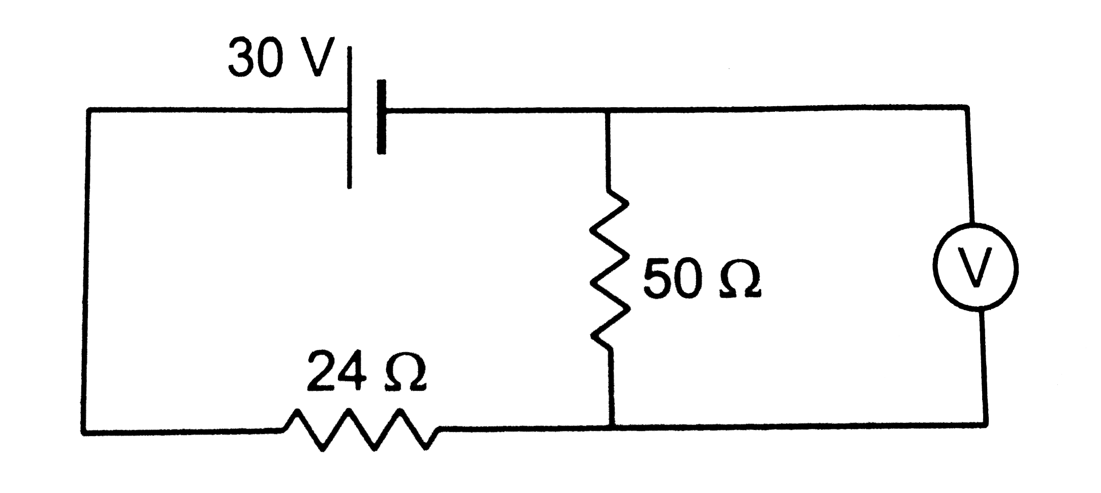
The voltmeter shown in figure reads 18V across the 50(Ω)resistor. Find the resistance of the voltmeter.
 View Solution
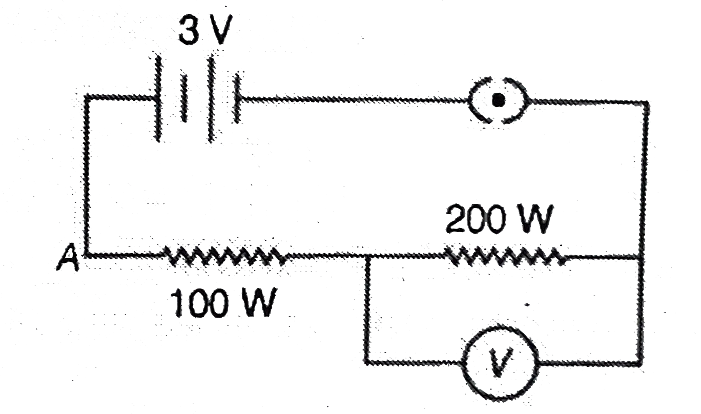
The voltmeter in figure has a resistance of 200Ω. The reading of voltmeter is
 View Solution
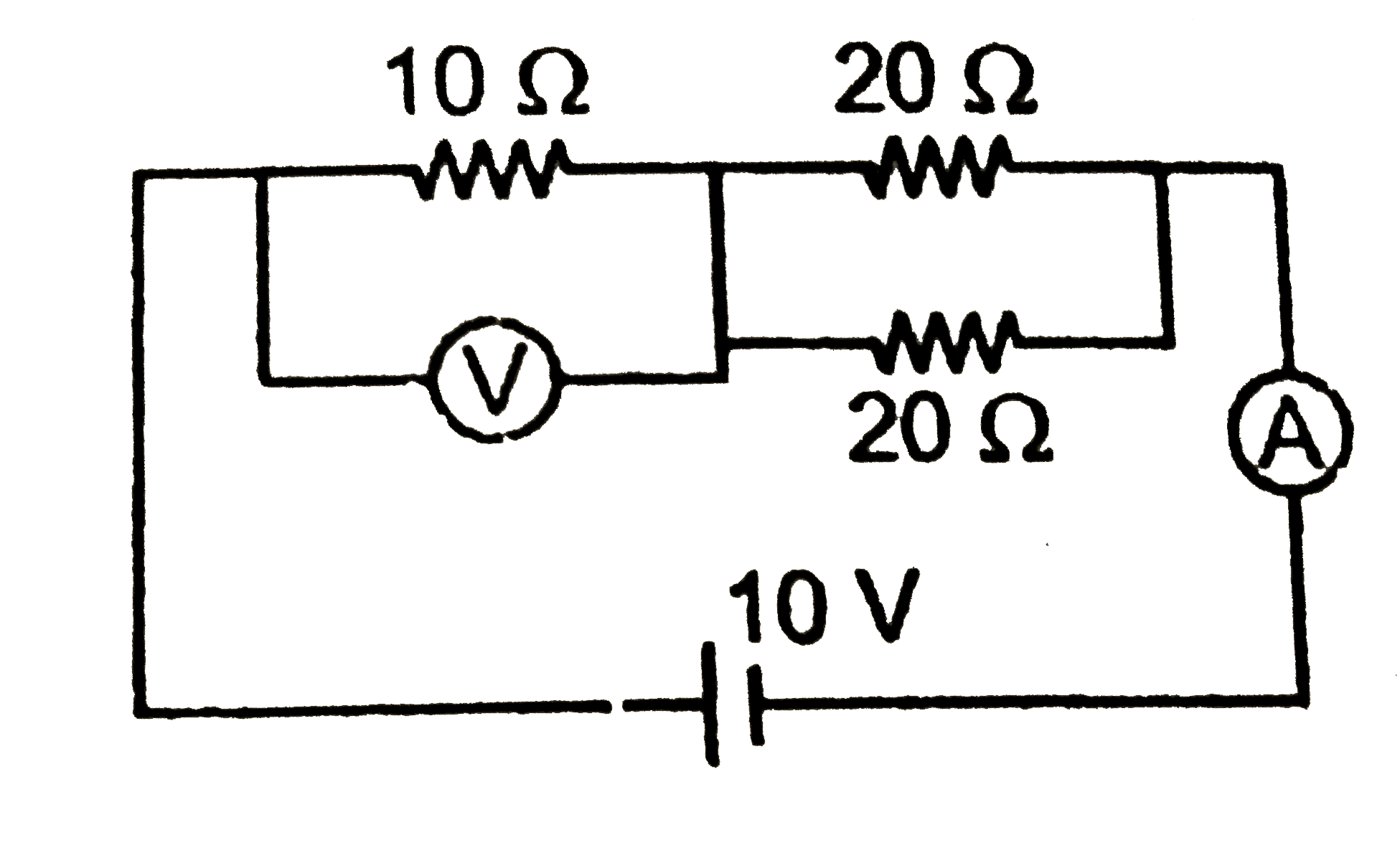
A circuit is shown in the figure. The ratio of readings of ideal voltmeter to reading of ideal ammeter is
 View Solution

