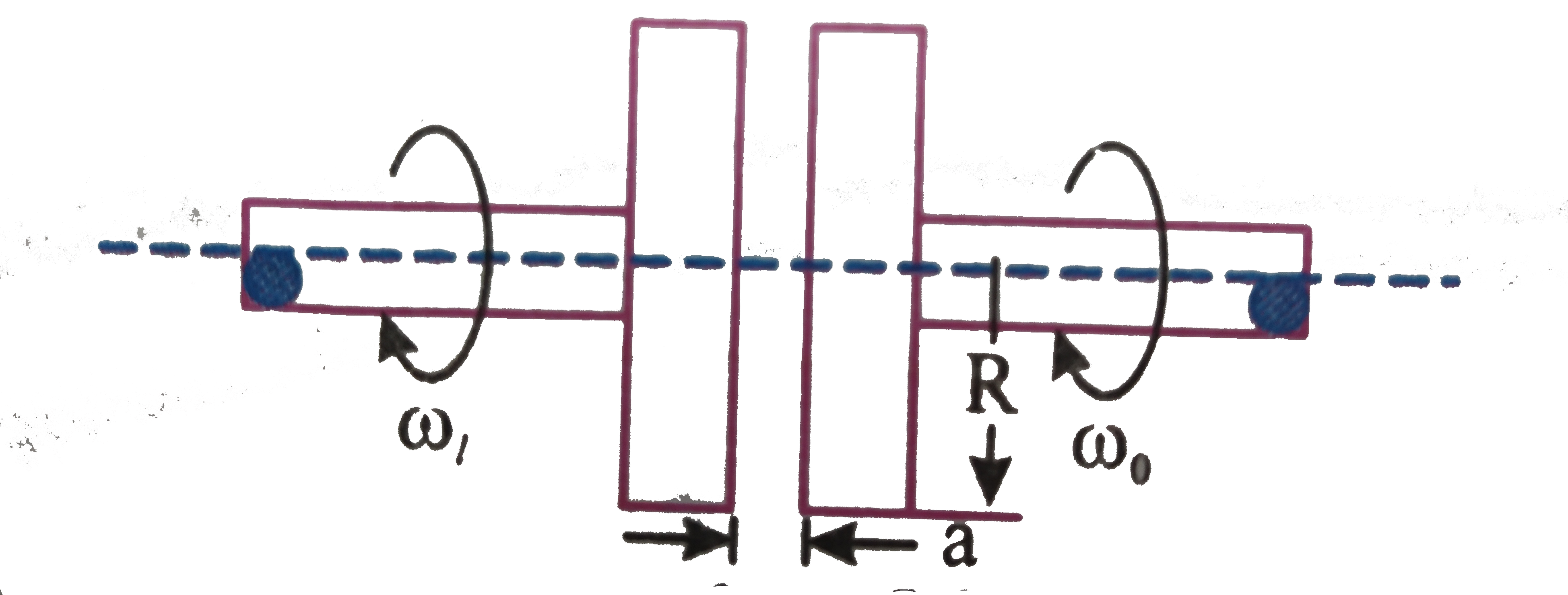
A viscous clutch as shown in figure tranmits torque. Radius of each clutch plate is R and separation between the plates is a and is completely filled with liquid of coefficient of viscous . If and are angular velocities of plates connected to input and output respectively.
If efficiency of transmission is ratio of output power to input power, then efficiency is given by
The correct Answer is:B
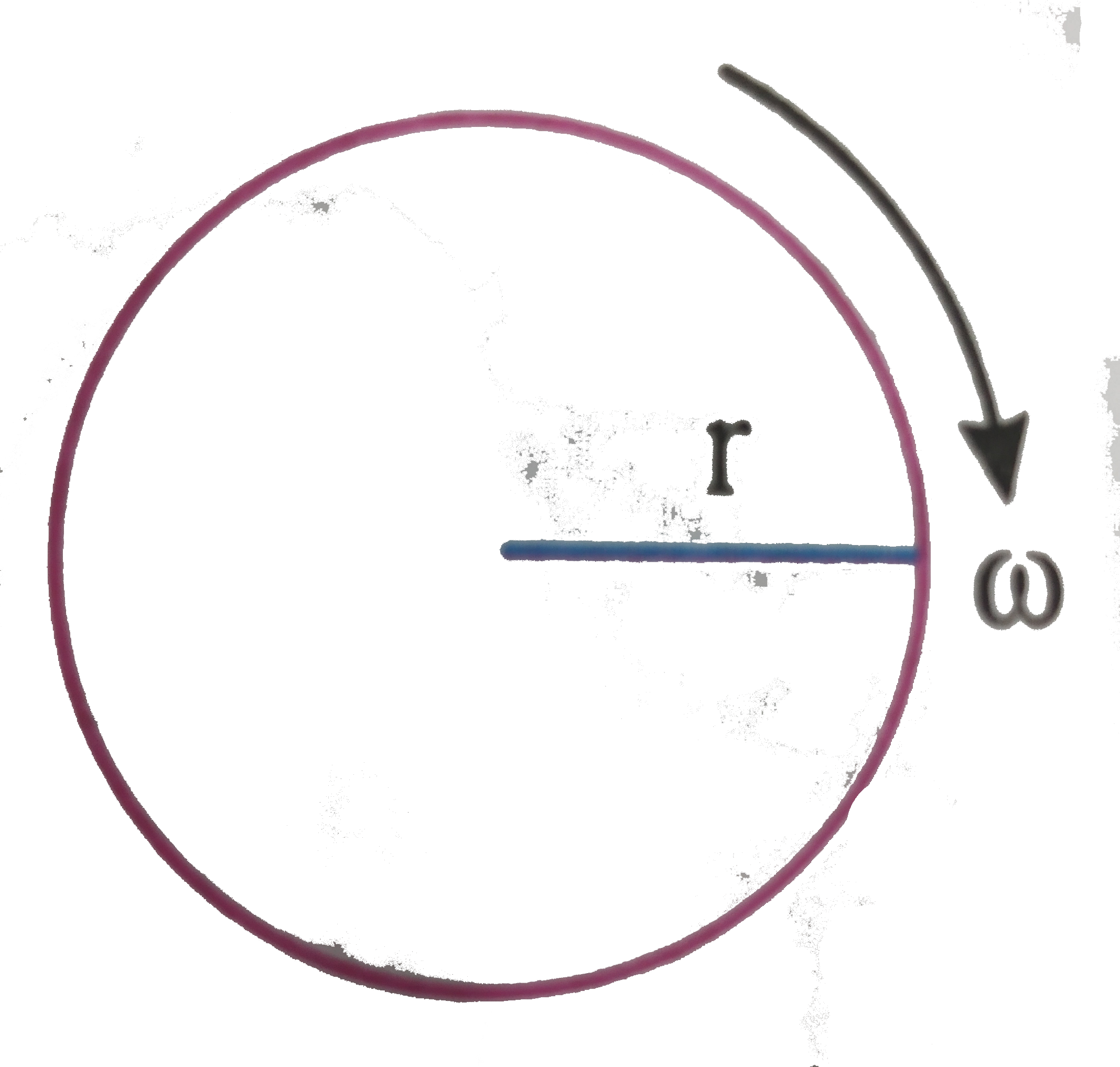
Let's consider a circular element of radius r and width dr, co-axial with the system.
Velocity difference across the element
Hence
These force are tangential and hence
Hence
Power (P)
Hence efficiency
Topper's Solved these Questions
- MECHANICAL PROPERTIES OF FLUIDSBook:NARAYNAChapter:MECHANICAL PROPERTIES OF FLUIDSExercise:Single Answer Questions
Explore 108 Videos
- MECHANICAL PROPERTIES OF FLUIDSBook:NARAYNAChapter:MECHANICAL PROPERTIES OF FLUIDSExercise:integer Type Questions
Explore 25 Videos
- MECHANICAL PROPERTIES OF FLUIDSBook:NARAYNAChapter:MECHANICAL PROPERTIES OF FLUIDSExercise:Comprehension Type Questions
Explore 40 Videos
- MATHEMATICAL REVIEW & PHYSICAL WORLDBook:NARAYNAChapter:MATHEMATICAL REVIEW & PHYSICAL WORLDExercise:C.U.Q
Explore 13 Videos
- MECHANICAL PROPERTIES OF SOLIDSBook:NARAYNAChapter:MECHANICAL PROPERTIES OF SOLIDSExercise:LEVEL-II (H.W)
Explore 24 Videos
Similar Questions
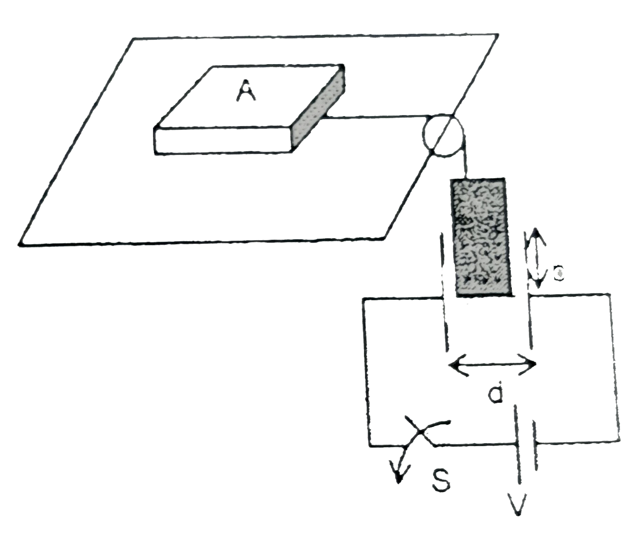
A block A of mass M kept on a rough horizontal surface is connected to a dielectric slab of mass M/6 and dielectric constant k by means of a light and inextensible string passing over a fixed pulley as shown in the figure. The dielectric can completely fill the space between the parallel plate capacitor of plate area l×l and separation between the plates d kept in vertical position. Initially switch S is open and length of the dielectric inside the capacitor is b. The coefficient of friction between the block A and the surface is μ=1/4. Igonore any other friction. (Given Mgdε0l(k−1)=24.)
Find the minimum value of the emf =V of the battery so that after closing the switch the block A will move.
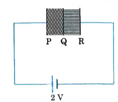
View SolutionThree metal plates P, Q and R of area A are connected across a battery of 2V as shown in the adjoining figure (p). Calculate the net capacitance if separation between plates P and Q is 0.2 cm and is completely filled with dielectric of dielectric constant 4, while separation between plates Q and R is 0.5 cm and is completely filled with a dielectric material of dielectric constant 6.
View Solution
Knowledge Check
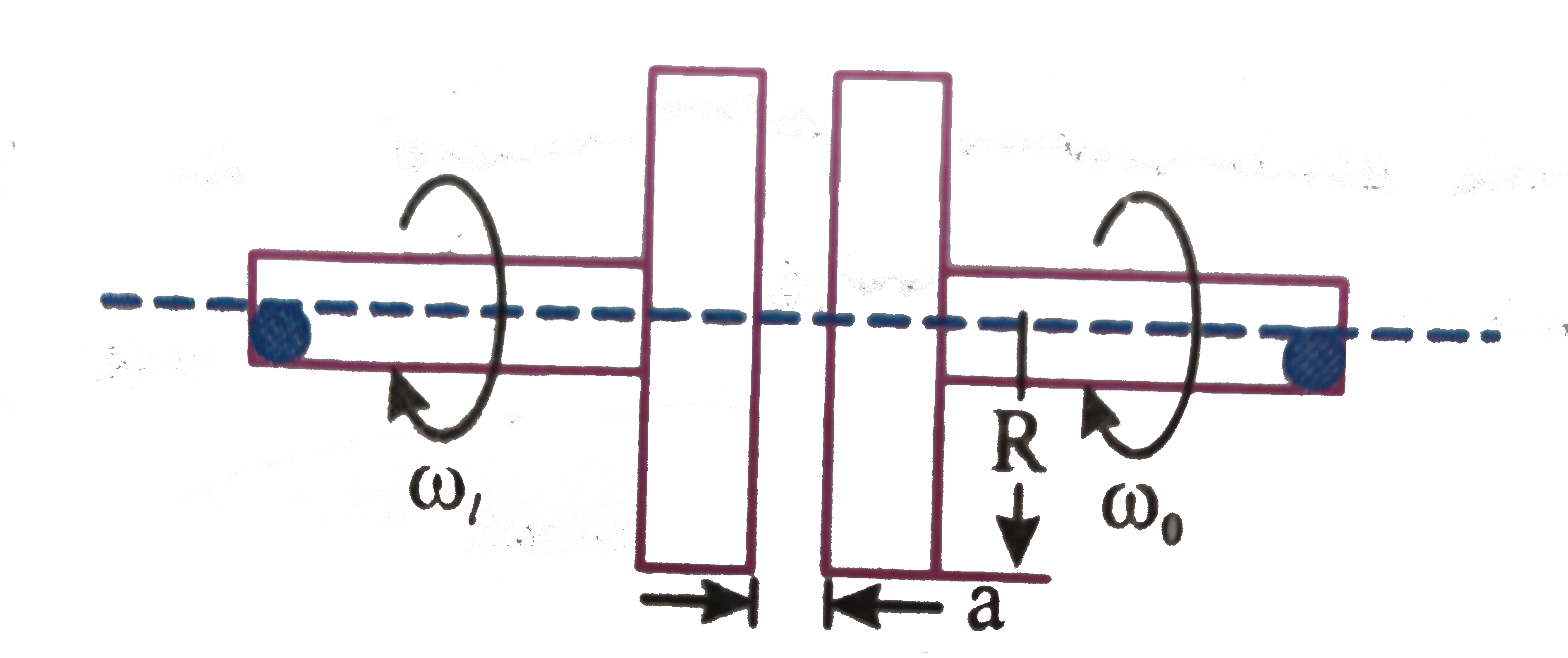
A viscous clutch as shown in figure tranmits torque. Radius of each clutch plate is R and separation between the plates is a and is completely filled with liquid of coefficient of viscous μ. If ωi and ω0 are angular velocities of plates connected to input and output respectively.
The torque transmitted isAπμ(ω2i−ω20)R4ωiaBπμ(ω2i−ω20)R4ω0aCπμ(ω2i−ω20)R42ω0aDπμ(ωi−ω0)R42aRead the following text and answer the following questions on the basis of the same:
Losses of transformer
There are 4 types of losses in a transformer: Core loss, Ohmic loss, Stray load loss and dielectric loss.
(1) Core loss
Core loss has two components - hysteresis loss and eddy current loss. These together are called no-load losses of a transformer and are calculated by open circuit test.
(a) Hysteresis loss: This loss mainly depends on the core material used in the transformer. To reduce this loss, the high-grade core material can be used. CRGO-Cold rolled grain oriented Si steel is commonly used for this purpose.
(b) Eddy current loss: This loss can be reduced by designing the core using slight laminations. These losses are present even when no load is connected. So, these are also known as no-load loss.
(2) Copper Loss
Copper losses occur because of the Ohmic resistance in the windings of the transformer. If the currents in primary and secondary windings of the transformer are I1 and I2 and if the resistances of these windings are R1 & R2 then the copper losses that occurred in the windings are I21R1 & I22R2 respectively. So, the entire copper loss will be I21R1+I22R2.
This loss is also called variable or ohmic losses because this loss changes based on the load.
(3) Stray Loss
These types of losses in a transformer occur because of the occurrence of the leakage flux. As compared with copper and iron losses, the percentage of stray losses are less, so these losses can be neglected.
(4) Dielectric Loss
This loss mainly occurs within the oil of the transformer. Oil is an insulating material. Once the oil quality in the transformer deteriorates then the transformer's efficiency is affected.
Efficiency of Transformer
It is the ratio of output power and input power.
Efficiency = Output Power /Input Power.
The transformer is a highly efficient device which ranges between 95% -98.5%.
Specify the range of transformer efficiency.A10−15%B95−98%C50−60%D40−50%Read the following text and answer the following questions on the basis of the same:
Losses of transformer
There are 4 types of losses in a transformer: Core loss, Ohmic loss, Stray load loss and dielectric loss.
(1) Core loss
Core loss has two components - hysteresis loss and eddy current loss. These together are called no-load losses of a transformer and are calculated by open circuit test.
(a) Hysteresis loss: This loss mainly depends on the core material used in the transformer. To reduce this loss, the high-grade core material can be used. CRGO-Cold rolled grain oriented Si steel is commonly used for this purpose.
(b) Eddy current loss: This loss can be reduced by designing the core using slight laminations. These losses are present even when no load is connected. So, these are also known as no-load loss.
(2) Copper Loss
Copper losses occur because of the Ohmic resistance in the windings of the transformer. If the currents in primary and secondary windings of the transformer are I1 and I2 and if the resistances of these windings are R1 & R2 then the copper losses that occurred in the windings are I21R1 & I22R2 respectively. So, the entire copper loss will be I21R1+I22R2.
This loss is also called variable or ohmic losses because this loss changes based on the load.
(3) Stray Loss
These types of losses in a transformer occur because of the occurrence of the leakage flux. As compared with copper and iron losses, the percentage of stray losses are less, so these losses can be neglected.
(4) Dielectric Loss
This loss mainly occurs within the oil of the transformer. Oil is an insulating material. Once the oil quality in the transformer deteriorates then the transformer's efficiency is affected.
Efficiency of Transformer
It is the ratio of output power and input power.
Efficiency = Output Power /Input Power.
The transformer is a highly efficient device which ranges between 95% -98.5%.
How hysteresis loss can be reduced?AUsing core of Si SteelBUsing laminated coreCUsing core of non-ferro magnetic materialDUsing oil of higher dielectric constant
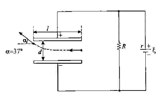
A parallel plate capacitor with plates of length l is included in a circuit as shown in figure-3.164. The EMF of the source is ε, its internal resistance is r and the distance between the plates is d. An electron with a velocity u files into the capacitor, parallel to the plates . What resistance R should be connected in parallel with the capacitor so that the electron files out of the capacitor at an angle of 37∘ to the plates? Assume that circuit is in steady state. Given values of parameters as l=91cmε=3V,r=2Ω,d=(1/3)mm,u=4×107m/sme=9.1×10−31kg and e=1.6×10⁻¹⁹C.
View SolutionRead the following text and answer the following questions on the basis of the same:
Losses of transformer
There are 4 types of losses in a transformer: Core loss, Ohmic loss, Stray load loss and dielectric loss.
(1) Core loss
Core loss has two components - hysteresis loss and eddy current loss. These together are called no-load losses of a transformer and are calculated by open circuit test.
(a) Hysteresis loss: This loss mainly depends on the core material used in the transformer. To reduce this loss, the high-grade core material can be used. CRGO-Cold rolled grain oriented Si steel is commonly used for this purpose.
(b) Eddy current loss: This loss can be reduced by designing the core using slight laminations. These losses are present even when no load is connected. So, these are also known as no-load loss.
(2) Copper Loss
Copper losses occur because of the Ohmic resistance in the windings of the transformer. If the currents in primary and secondary windings of the transformer are I1 and I2 and if the resistances of these windings are R1 & R2 then the copper losses that occurred in the windings are I21R1 & I22R2 respectively. So, the entire copper loss will be I21R1+I22R2.
This loss is also called variable or ohmic losses because this loss changes based on the load.
(3) Stray Loss
These types of losses in a transformer occur because of the occurrence of the leakage flux. As compared with copper and iron losses, the percentage of stray losses are less, so these losses can be neglected.
(4) Dielectric Loss
This loss mainly occurs within the oil of the transformer. Oil is an insulating material. Once the oil quality in the transformer deteriorates then the transformer's efficiency is affected.
Efficiency of Transformer
It is the ratio of output power and input power.
Efficiency = Output Power /Input Power.
The transformer is a highly efficient device which ranges between 95% -98.5%.
What is the relationship among core loss, hysteresis loss and eddy current loss?
View SolutionRead the following text and answer the following questions on the basis of the same:
Losses of transformer
There are 4 types of losses in a transformer: Core loss, Ohmic loss, Stray load loss and dielectric loss.
(1) Core loss
Core loss has two components - hysteresis loss and eddy current loss. These together are called no-load losses of a transformer and are calculated by open circuit test.
(a) Hysteresis loss: This loss mainly depends on the core material used in the transformer. To reduce this loss, the high-grade core material can be used. CRGO-Cold rolled grain oriented Si steel is commonly used for this purpose.
(b) Eddy current loss: This loss can be reduced by designing the core using slight laminations. These losses are present even when no load is connected. So, these are also known as no-load loss.
(2) Copper Loss
Copper losses occur because of the Ohmic resistance in the windings of the transformer. If the currents in primary and secondary windings of the transformer are I1 and I2 and if the resistances of these windings are R1 & R2 then the copper losses that occurred in the windings are I21R1 & I22R2 respectively. So, the entire copper loss will be I21R1+I22R2.
This loss is also called variable or ohmic losses because this loss changes based on the load.
(3) Stray Loss
These types of losses in a transformer occur because of the occurrence of the leakage flux. As compared with copper and iron losses, the percentage of stray losses are less, so these losses can be neglected.
(4) Dielectric Loss
This loss mainly occurs within the oil of the transformer. Oil is an insulating material. Once the oil quality in the transformer deteriorates then the transformer's efficiency is affected.
Efficiency of Transformer
It is the ratio of output power and input power.
Efficiency = Output Power /Input Power.
The transformer is a highly efficient device which ranges between 95% -98.5%.
Which of the following losses in transformer is also known as no-load loss?
View SolutionRead the following text and answer the following questions on the basis of the same:
Losses of transformer
There are 4 types of losses in a transformer: Core loss, Ohmic loss, Stray load loss and dielectric loss.
(1) Core loss
Core loss has two components - hysteresis loss and eddy current loss. These together are called no-load losses of a transformer and are calculated by open circuit test.
(a) Hysteresis loss: This loss mainly depends on the core material used in the transformer. To reduce this loss, the high-grade core material can be used. CRGO-Cold rolled grain oriented Si steel is commonly used for this purpose.
(b) Eddy current loss: This loss can be reduced by designing the core using slight laminations. These losses are present even when no load is connected. So, these are also known as no-load loss.
(2) Copper Loss
Copper losses occur because of the Ohmic resistance in the windings of the transformer. If the currents in primary and secondary windings of the transformer are I1 and I2 and if the resistances of these windings are R1 & R2 then the copper losses that occurred in the windings are I21R1 & I22R2 respectively. So, the entire copper loss will be I21R1+I22R2.
This loss is also called variable or ohmic losses because this loss changes based on the load.
(3) Stray Loss
These types of losses in a transformer occur because of the occurrence of the leakage flux. As compared with copper and iron losses, the percentage of stray losses are less, so these losses can be neglected.
(4) Dielectric Loss
This loss mainly occurs within the oil of the transformer. Oil is an insulating material. Once the oil quality in the transformer deteriorates then the transformer's efficiency is affected.
Efficiency of Transformer
It is the ratio of output power and input power.
Efficiency = Output Power /Input Power.
The transformer is a highly efficient device which ranges between 95% -98.5%.
Which of the following losses in transformer is also known as variable loss?
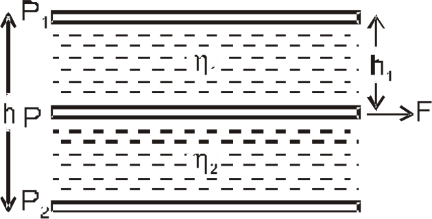
View SolutionA thin horizontal movable plate P is separated from two fixed horizontal plates P1 and P2 by two highly viscous liquids of coefficient of viscosity η1 and η2 as shown, where η2=4η1. Area of contact of movable plate with each fluid is same. If the distance between two fixed plates is h, then the distance h1 of movable plate from upper fixed plate such that the movable plate can be moved with a constant velocity by applying a minimum constant horizontal force F on movable plate is (assume velocity gradient to be uniform in each liquid).
View Solution

