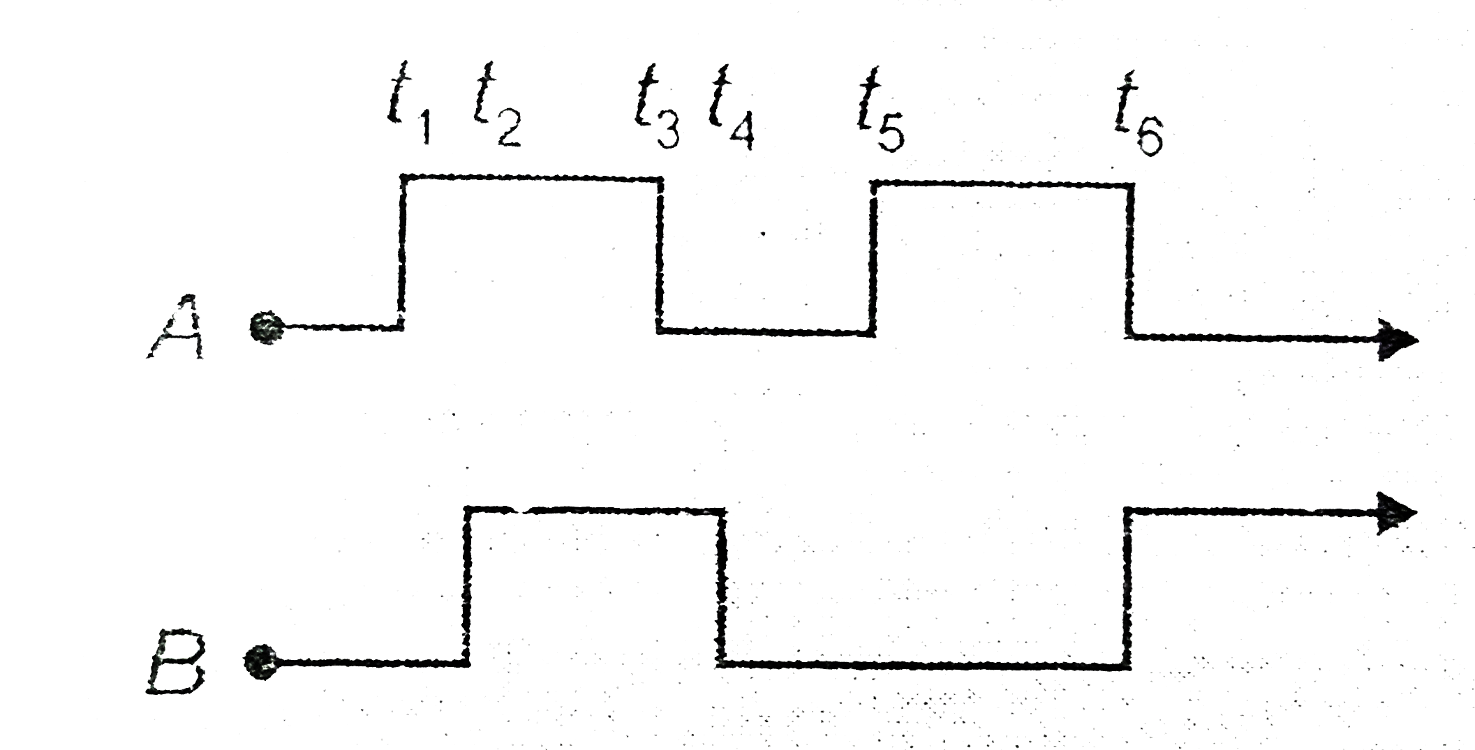
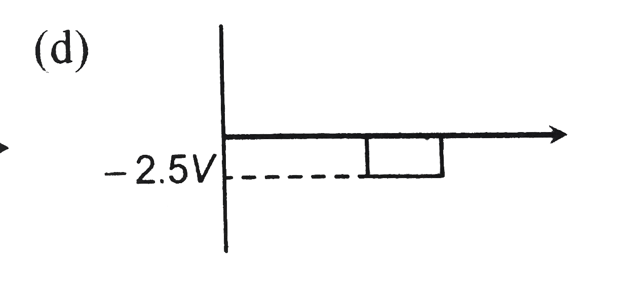
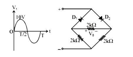
A waveform shown when applied to the following circuit will produce which of the following output waveform? [Assuming ideal diode configuration and R1=R2]
![A waveform shown when applied to the following circuit will produce which of the following output waveform? [Assuming ideal diode configuration and R(1)=R(2)]](https://d10lpgp6xz60nq.cloudfront.net/physics_images/BMS_OBJ_XII_C13_E01_192_Q01.png)
A
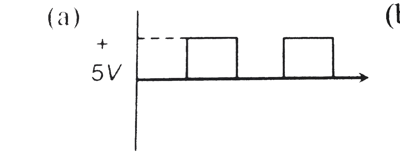
B
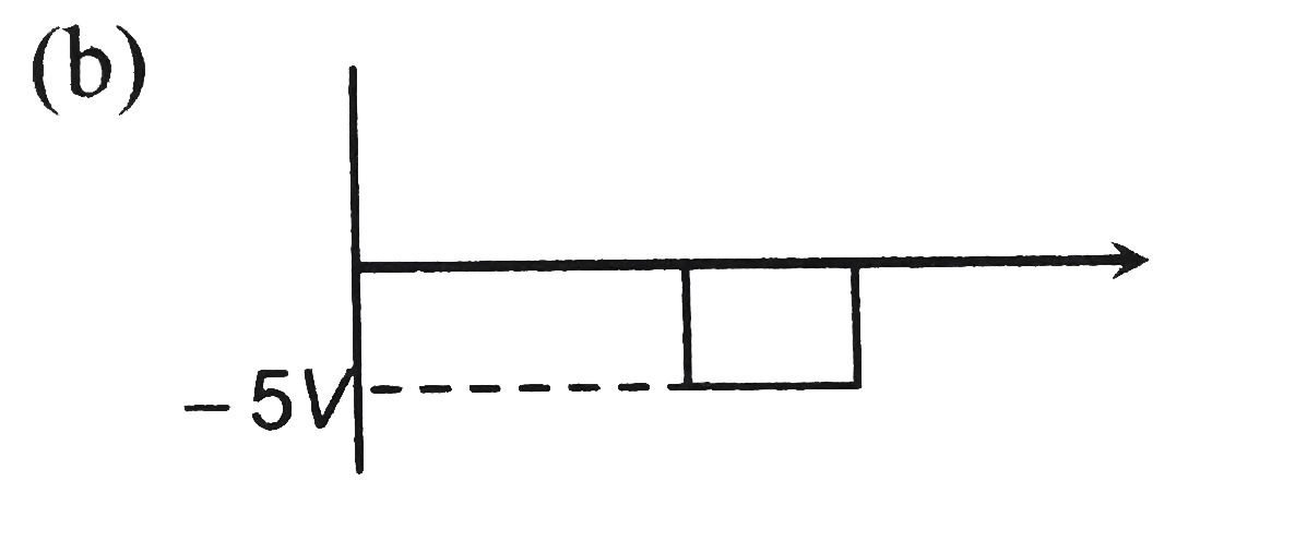
C
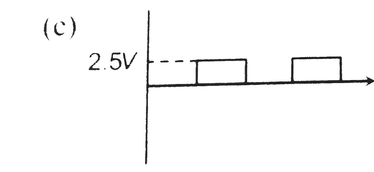
D
Video Solution
Text Solution
The correct Answer is:D
The P−N junction will conduct only when it is forward biased i.e., when −5V is fed to it, so it will conduct only for 3rd quarter part of signal shown and when it conducts potential drop 5 volt will be across both the resistor, so output voltage across R2 is 2.5V.
∴V0=−2.5V
|
Topper's Solved these Questions
- SEMICONDUCTOR ELECTRONICSBOOK - A2ZCHAPTER - SEMICONDUCTOR ELECTRONICSEXERCISE - Junction Transistor
47 Videos
- SEMICONDUCTOR ELECTRONICSBOOK - A2ZCHAPTER - SEMICONDUCTOR ELECTRONICSEXERCISE - Digital Electronics
40 Videos
- SEMICONDUCTOR ELECTRONICSBOOK - A2ZCHAPTER - SEMICONDUCTOR ELECTRONICSEXERCISE - Junction Diode
57 Videos
- NUCLEAR PHYSICSBOOK - A2ZCHAPTER - NUCLEAR PHYSICSEXERCISE - Section D - Chapter End Test
29 Videos
- SOURCE AND EFFECT OF MAGNETIC FIELDBOOK - A2ZCHAPTER - SOURCE AND EFFECT OF MAGNETIC FIELDEXERCISE - Section D - Chapter End Test
30 Videos
Similar Questions
Knowledge Check
Which of the following has R configuration ?
A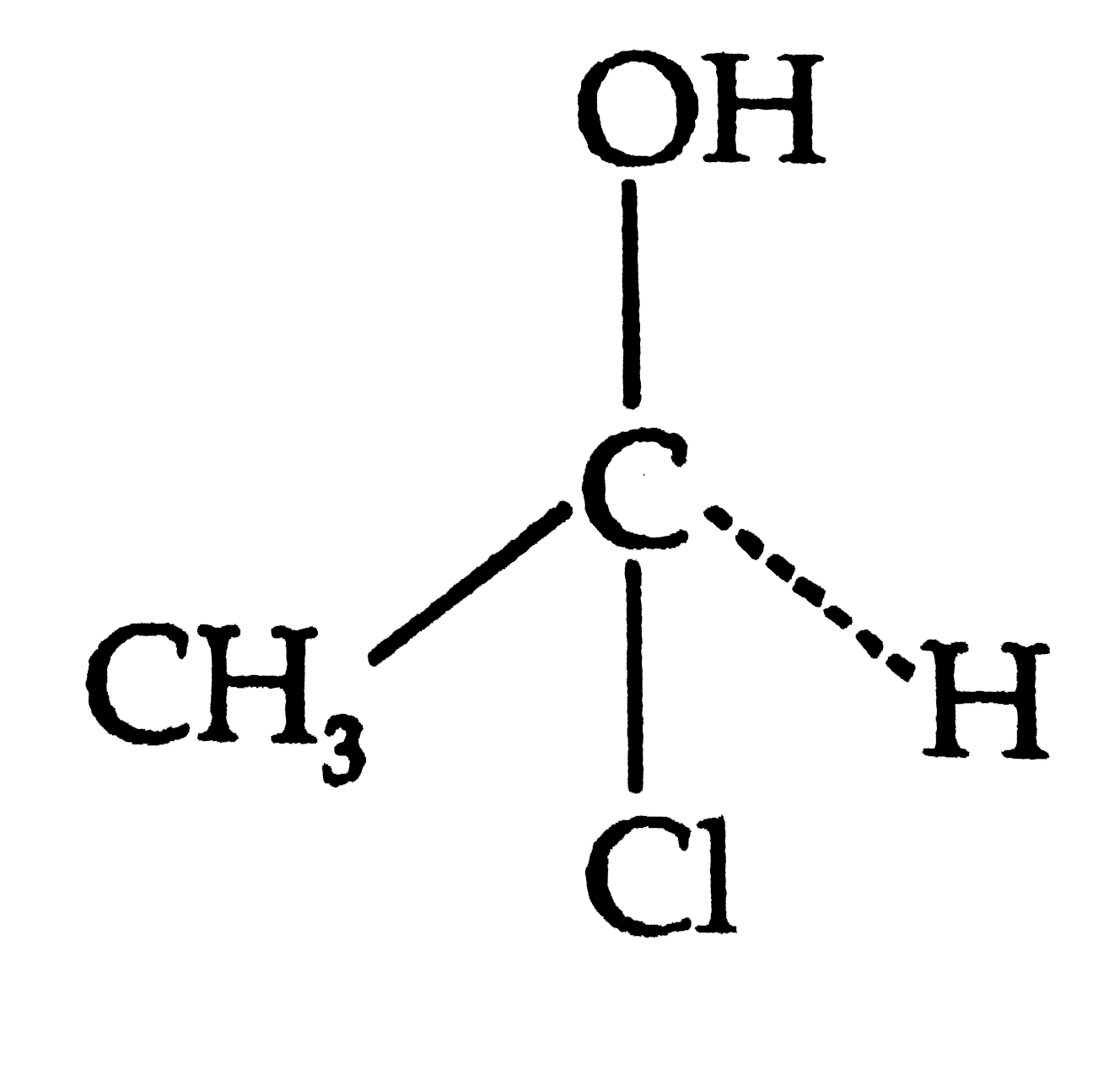 B
B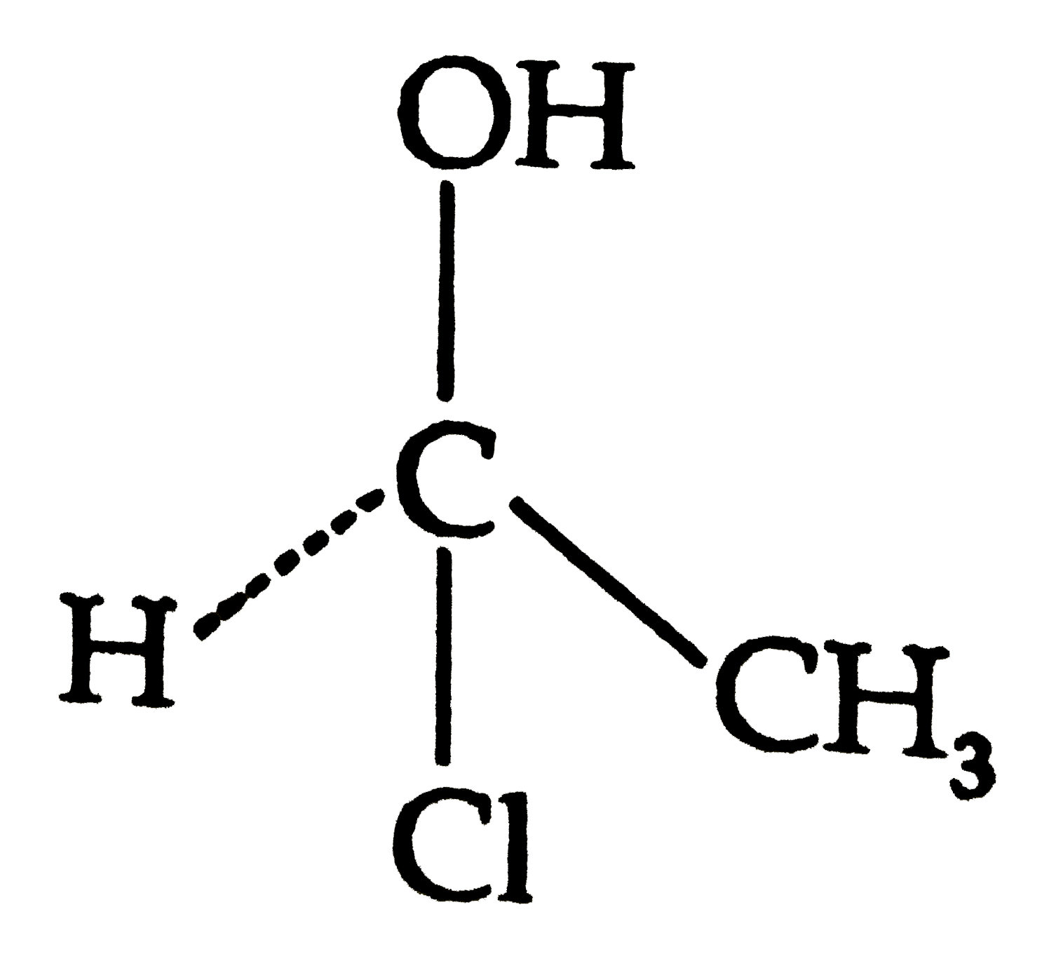 C
C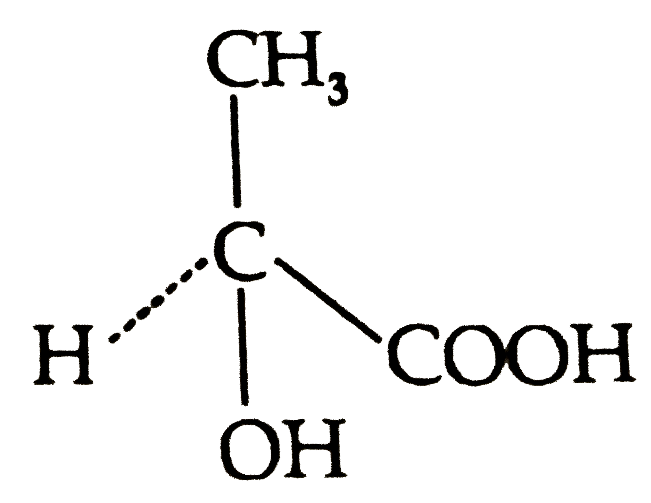 D
D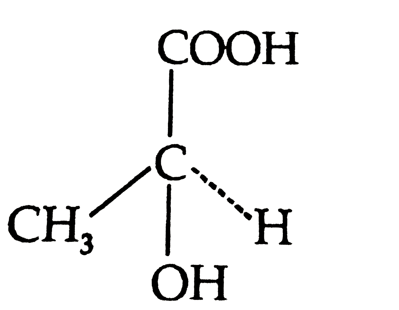
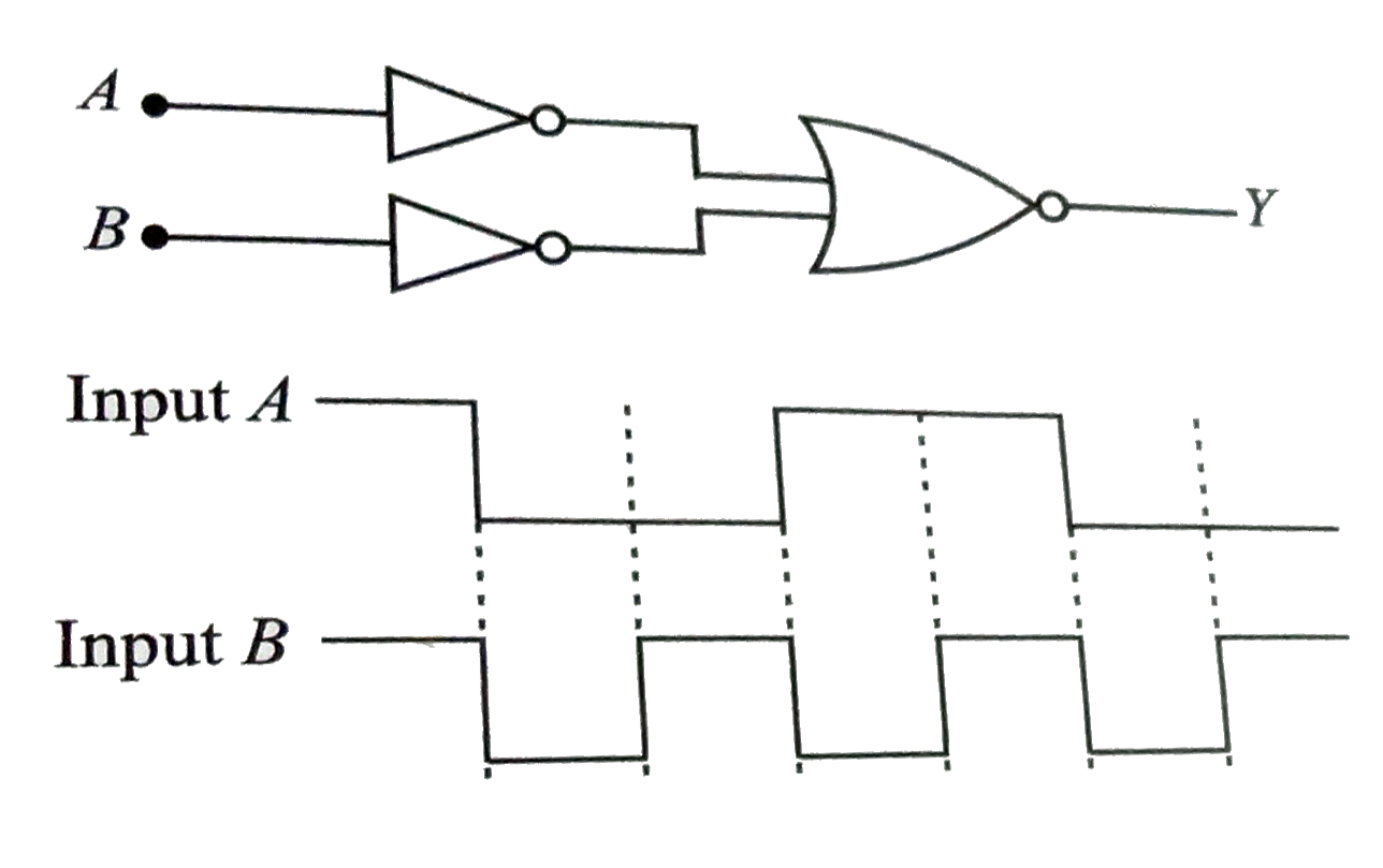
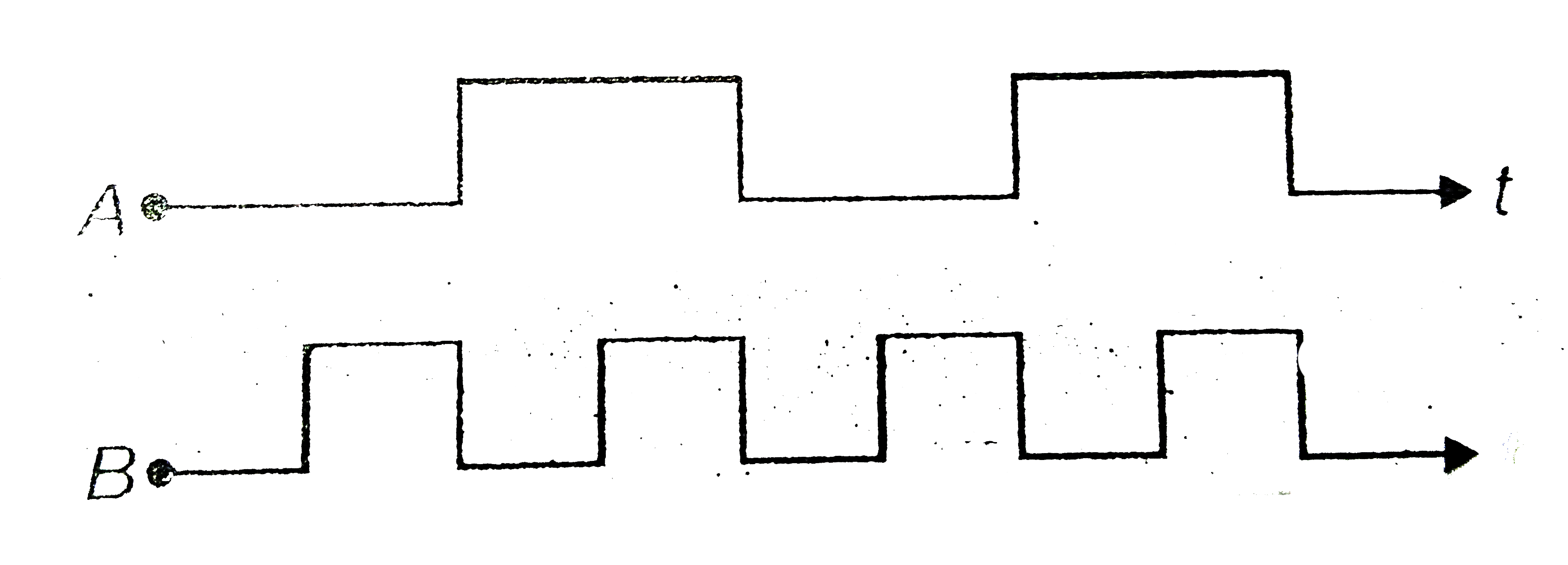
The logic circuit shown below has the inputs waveforms A and B as shown. Pick out the correct output waveform.
 A
A B
B C
C D
D
In the following circuit i1 and i2 are respectively
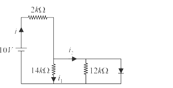 A0,0B0,5mAC5mA,0D5mA, 5mA
show the output waveform of AND gate for the following input waveforms of A and B.

View SolutionIn the half-wave rectifier circuit shown, which one of the following waveform is true for VCD the output across C and D?

View SolutionChoose the correct waveform that can represent the voltage across R of the following circuit, assuming the diode is ideal one :
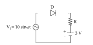
View SolutionIn circuit shown in figure, determine the output waveform, output d.c. level of 'V'0 :
View SolutionSketch the output waveform Y from a NAND gate having following inputs A and B
View Solution


