The peak voltage in the output of a half-wave diode rectifier fed with a sinusiodal signal without filter is 10V. The dc component of the output voltage is
10/√2V
10/πV
10V
20/πV
The correct Answer is:B
To find the DC component of the output voltage from a half-wave diode rectifier fed with a sinusoidal signal, we can follow these steps:
1. Identify the Peak Voltage:
The peak voltage (V_peak) given in the problem is 10 V.
2. Understand the Half-Wave Rectification:
In a half-wave rectifier, only one half (positive or negative) of the AC signal is allowed to pass through, while the other half is blocked. This results in a pulsating DC output.
3. Formula for DC Component:
The DC component (V_dc) of the output voltage for a half-wave rectifier can be calculated using the formula:
Vdc=Vpeakπ
4. Substitute the Peak Voltage:
Now, substitute the given peak voltage into the formula:
Vdc=10Vπ
5. Calculate the Value:
Using the approximate value of π≈3.14:
Vdc≈103.14≈3.18V
6. Final Answer:
Therefore, the DC component of the output voltage is approximately 3.18 V.
Summary of the Solution:
The DC component of the output voltage from a half-wave diode rectifier with a peak voltage of 10 V is approximately 3.18 V.
The peak voltage (V_peak) given in the problem is 10 V.
In a half-wave rectifier, only one half (positive or negative) of the AC signal is allowed to pass through, while the other half is blocked. This results in a pulsating DC output.
The DC component (V_dc) of the output voltage for a half-wave rectifier can be calculated using the formula:
Vdc=Vpeakπ
Now, substitute the given peak voltage into the formula:
Vdc=10Vπ
Using the approximate value of π≈3.14:
Vdc≈103.14≈3.18V
Therefore, the DC component of the output voltage is approximately 3.18 V.
The DC component of the output voltage from a half-wave diode rectifier with a peak voltage of 10 V is approximately 3.18 V.
Topper's Solved these Questions
- SEMICONDUCTOR ELECTRONICSBOOK - A2ZCHAPTER - SEMICONDUCTOR ELECTRONICSEXERCISE - Junction Transistor
47 Videos
- SEMICONDUCTOR ELECTRONICSBOOK - A2ZCHAPTER - SEMICONDUCTOR ELECTRONICSEXERCISE - Digital Electronics
40 Videos
- SEMICONDUCTOR ELECTRONICSBOOK - A2ZCHAPTER - SEMICONDUCTOR ELECTRONICSEXERCISE - Junction Diode
57 Videos
- NUCLEAR PHYSICSBOOK - A2ZCHAPTER - NUCLEAR PHYSICSEXERCISE - Section D - Chapter End Test
29 Videos
- SOURCE AND EFFECT OF MAGNETIC FIELDBOOK - A2ZCHAPTER - SOURCE AND EFFECT OF MAGNETIC FIELDEXERCISE - Section D - Chapter End Test
30 Videos
Similar Questions
Take the breakdown voltage of the zener diode used in the given circuit as 6V. For the input voltage shown in figure below , the time variation of the output voltage is : (Graphs drawn are schematic and not to scale )

View SolutionDraw the circuit diagram of half wave rectifier, showing input and output voltages.
View Solution
Knowledge Check
The peak voltage in the output of a half-wave diode rectifier fed with a sinusiodal signal without filter is 10V. The dc component of the output voltage is
A10√2VB10πVC10VD20πVIf the input frequency of half-wave rectifier is nHzac, then its output is
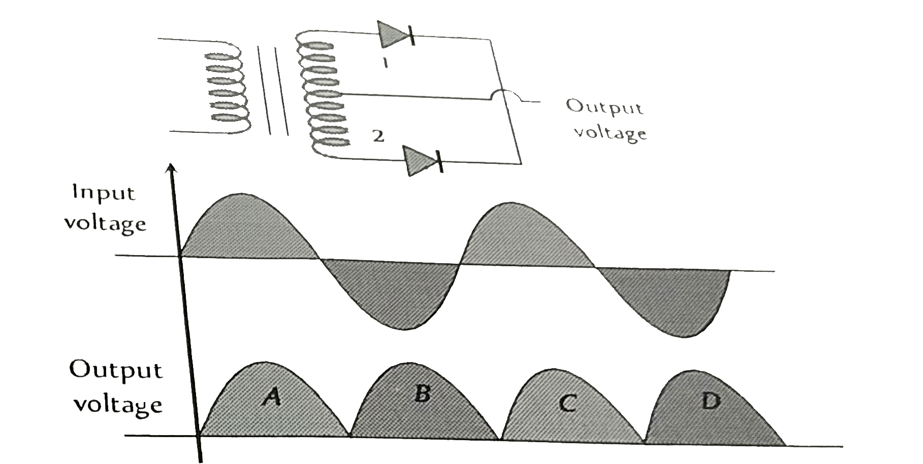
Aa constant dcBn/2Hz pulsating dcCnHz pulsating dcD2nHz pulsating dcA full wave rectifier circuit along with the input and output voltages is shown in the figure

The contribution to output voltage from diode – 2 isAA,CBB,DCB,CDA,D
Draw the cirucit of full wave recitfier with capacitor filter also draw the input and output voltage of this circuit
View SolutionThe amplifiers X,Y and Z are connected in series. If the voltage gains of X,Y and Z are 10,20 and 30, respectively and the input signal is 1mV peak value, then what is the output signal voltage (peak value)
(i) if dc supply voltage is 10V ?
(ii) if dc supply voltage is 5V?
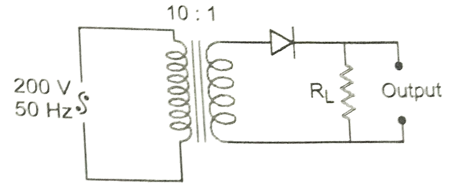
View SolutionFind the average value of d.c. voltage that can be obtained from the half wave rectifier of Fig. assuming that the diode is ideal one.

View SolutionA junction diode of negligible forward resistance is used as a half-wave rectifier for a sinusoidal voltage supply 24√2V(RMS), 50 Hz. The reading of D.C. voltmeter connected across the capacitor of 22μF which is in turn connected in parallel to the output load resistance RL of 20kΩ is _____ V.
View SolutionIn a common base ampifier , the phase difference between the input signal and output voltage is
View Solution