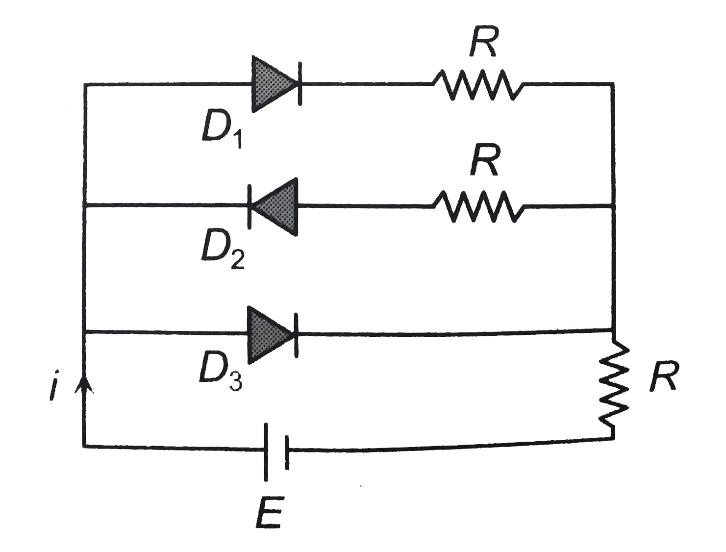
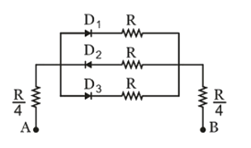
In the following circuit of PN junction diodes D1,D2 and D3 are ideal then i is
A
E/R
B
E/2R
C
2E/3R
D
Zero
Video Solution
Text Solution
The correct Answer is:A
Diodes D1 and D3 are forward biased and D2 is reverse biased on the circuit can be redrawn as follows.
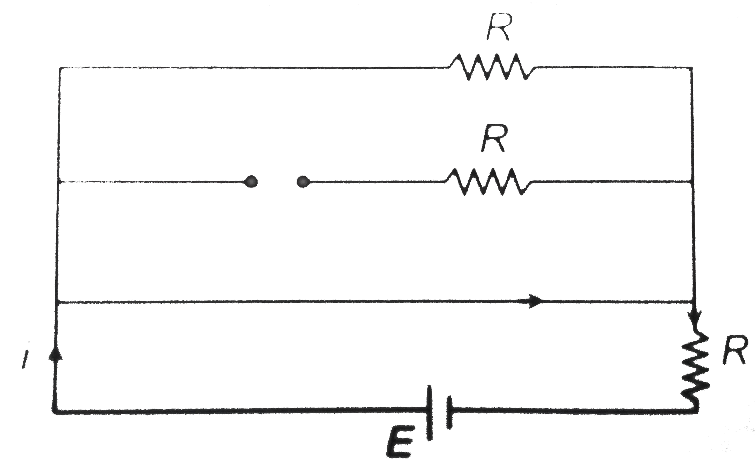
⇒i=ER
|
Topper's Solved these Questions
- SEMICONDUCTOR ELECTRONICSBOOK - A2ZCHAPTER - SEMICONDUCTOR ELECTRONICSEXERCISE - Junction Transistor
47 Videos
- SEMICONDUCTOR ELECTRONICSBOOK - A2ZCHAPTER - SEMICONDUCTOR ELECTRONICSEXERCISE - Digital Electronics
40 Videos
- SEMICONDUCTOR ELECTRONICSBOOK - A2ZCHAPTER - SEMICONDUCTOR ELECTRONICSEXERCISE - Junction Diode
57 Videos
- NUCLEAR PHYSICSBOOK - A2ZCHAPTER - NUCLEAR PHYSICSEXERCISE - Section D - Chapter End Test
29 Videos
- SOURCE AND EFFECT OF MAGNETIC FIELDBOOK - A2ZCHAPTER - SOURCE AND EFFECT OF MAGNETIC FIELDEXERCISE - Section D - Chapter End Test
30 Videos
Similar Questions
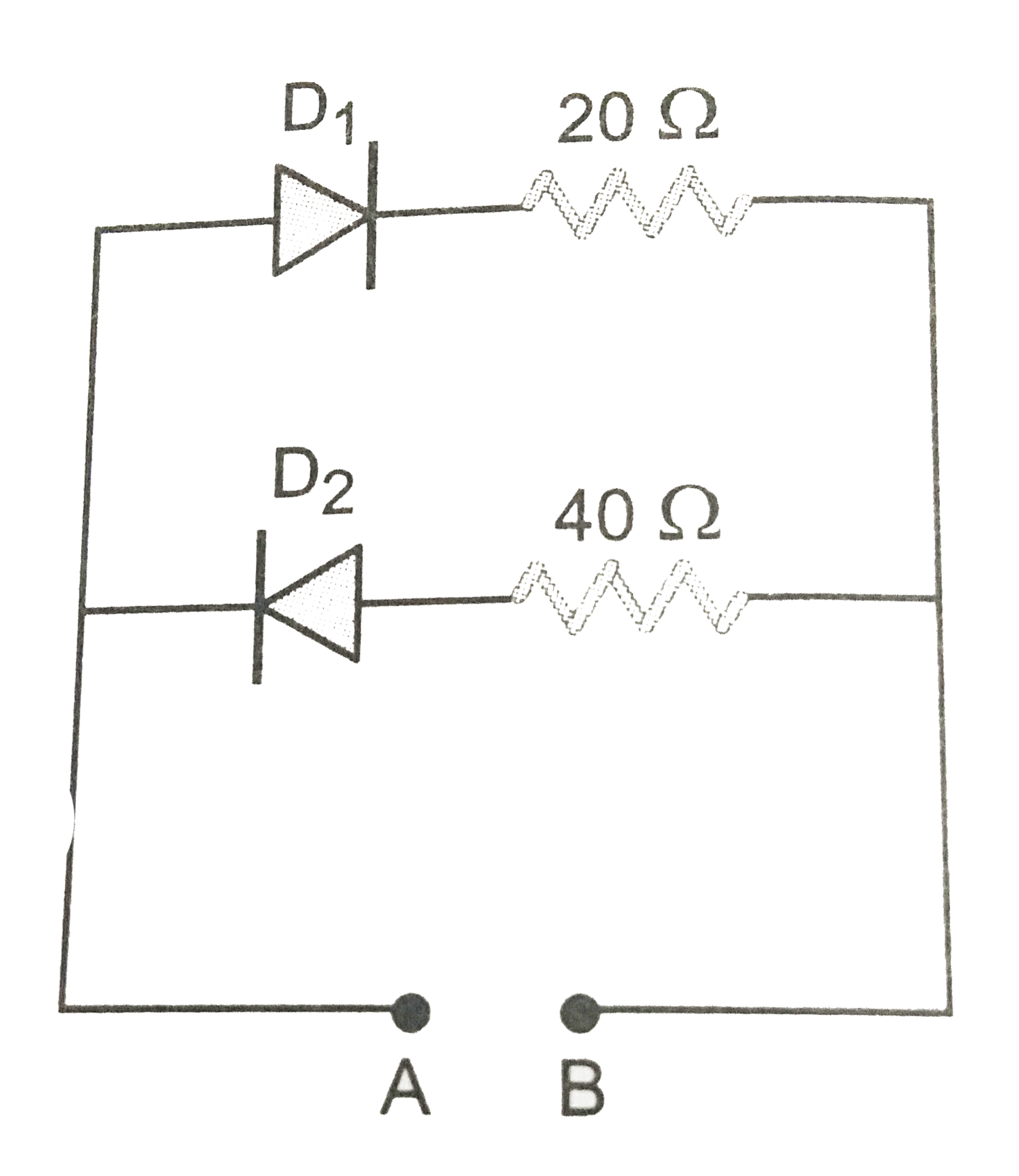
A battery of 1.5V may be connected across the point A and B as shown in Fig . What is the current drawn from the battery if the positive terminal of the battery is connected to the point A and the point B. The junction diodes D1 and D2 used are ideal diodes.
View SolutionWhat is an ideal junction diode?
View Solution
Knowledge Check
In the following circuits PN-junction diodes D1,D2 and D3 are ideal for the following potential of A and B, the correct increasing order to resistance between A and B will be
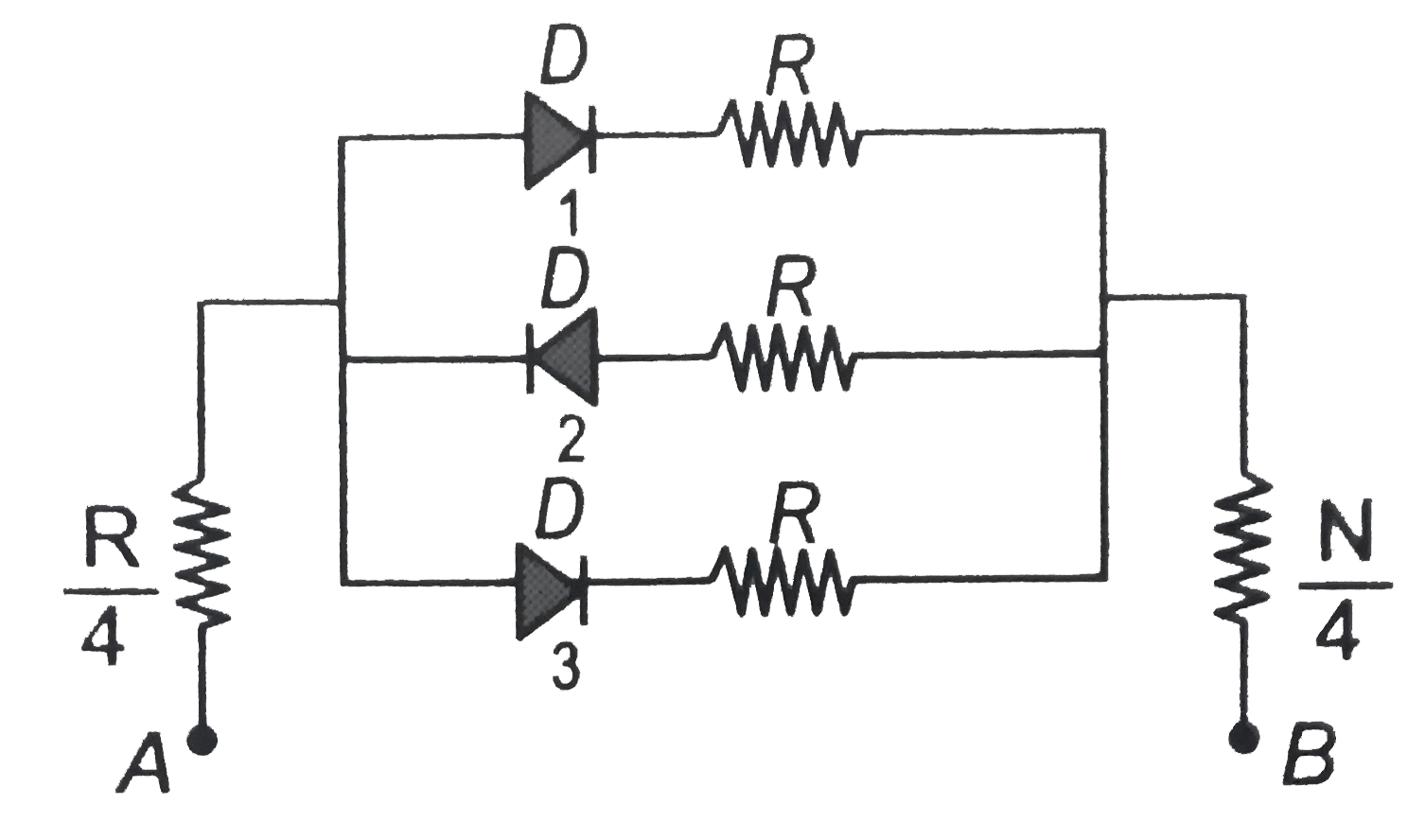
(i)−10V,−5V(ii)−5V,−10V
(iii)−4V,−12VA(i)<(ii)<(iii)B(iii)<(ii)<(i)C(ii)=(iii)<(i)D(i)=(iii)<(ii)In the following circuits, PN - junction diodes D1,D2andD3 are ideal for the following potential of A and B, the correct increasing order of resistance between A and B will be
(i) −10V,−5V
(ii) −5V,−10V
(iii) −4V,−12VA(i) lt (ii) lt (iii)B(iii) lt (ii) lt (i)C(ii) = (iii) lt (i)D(i) = (iii) lt (ii)In a PN -junction diode
AThe current in the reverse biased condition is generally very smallBThe current in the reverse biased condition is small but the forwards biased current is independent of the biase voltageCThe reverse biased current is srongly dependent on the applied biase voltage.DThe forward biased current is very small in comparision to reverse biased current.
The PN junction diode is used as
View SolutionThe reverse biasing in a PN junction diode
View SolutionIn the forward biase arrangement of a PN-junction diode
View SolutionAvalanche breakdown in a PN junction diode is to
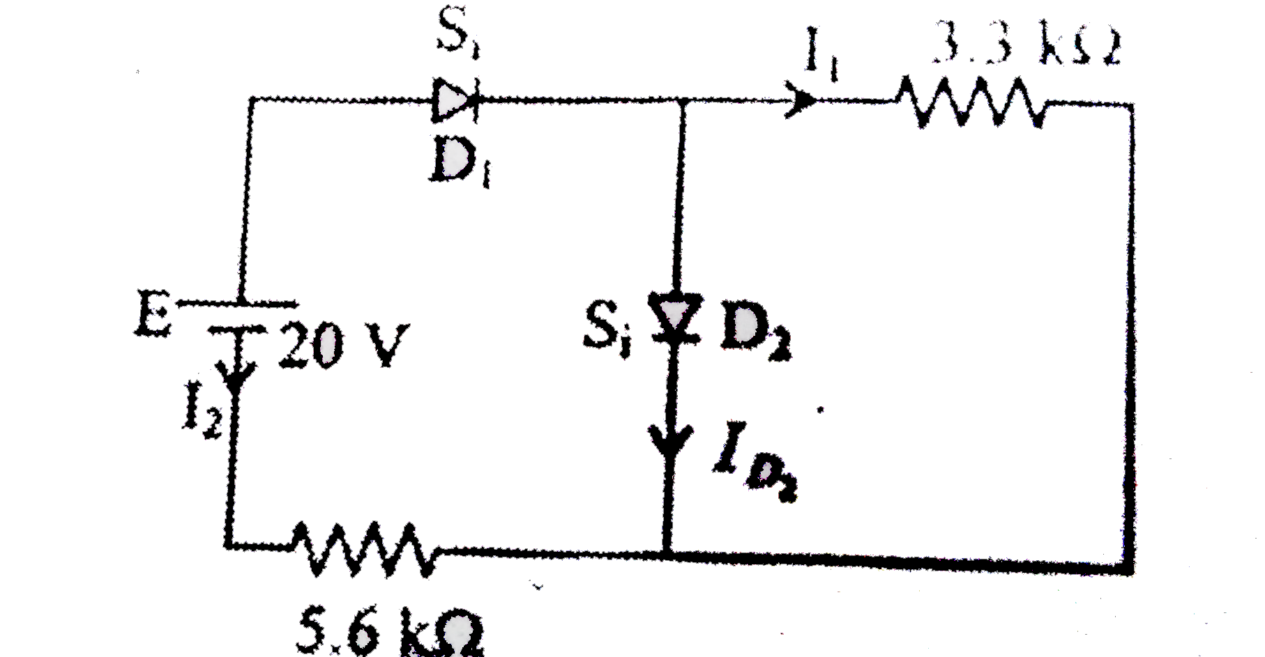
View SolutionIn the circuit shown in figure I1,I2 and ID2 are respectively-
View Solution
