In the following circuits PN-junction diodes D1,D2 and D3 are ideal for the following potential of A and B, the correct increasing order to resistance between A and B will be
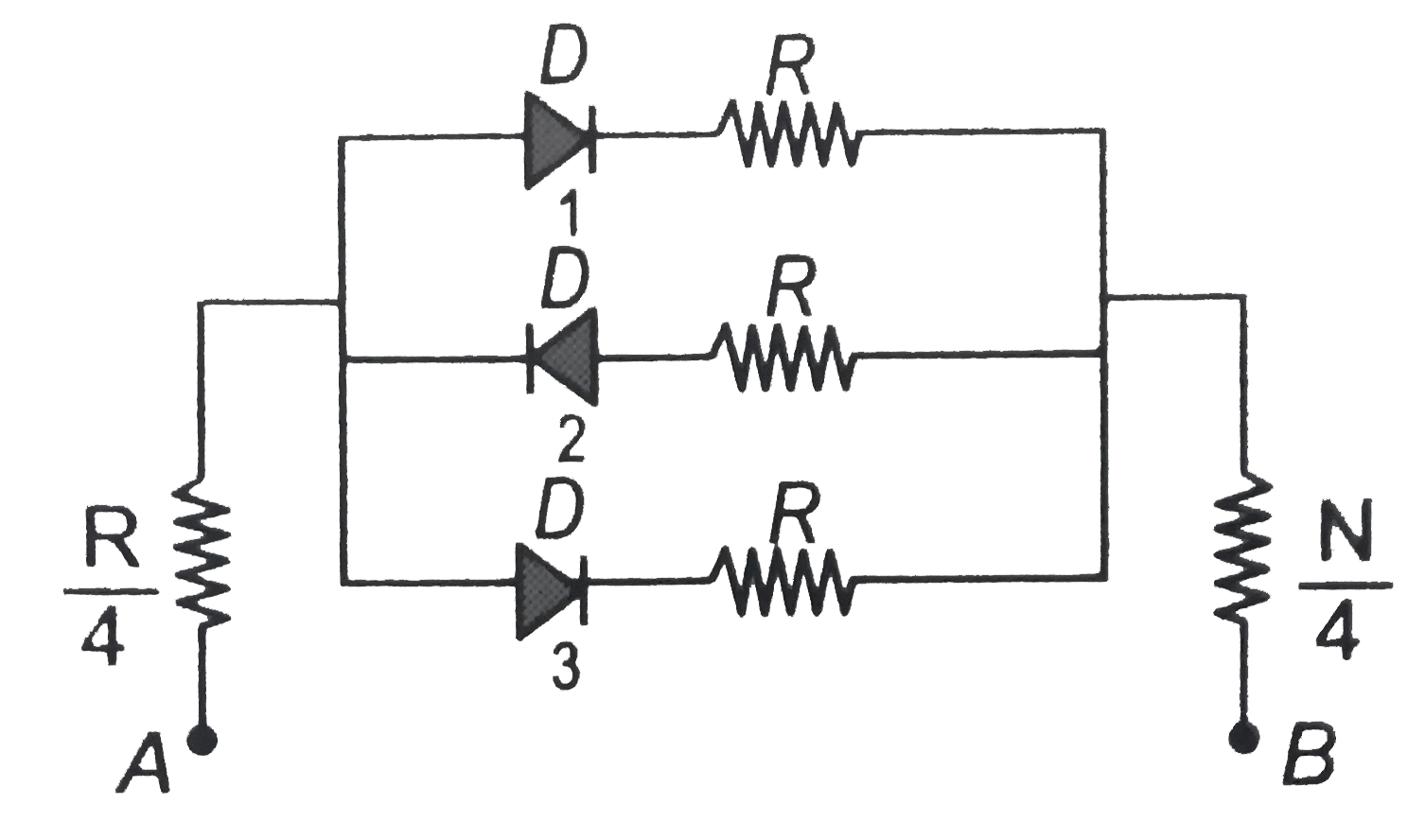
(i)−10V,−5V(ii)−5V,−10V
(iii)−4V,−12V
(i)<(ii)<(iii)
(iii)<(ii)<(i)
(ii)=(iii)<(i)
(i)=(iii)<(ii)
The correct Answer is:C
(i)VA=−10V and VB=−5V
Diodes D1 and D2 are reverse biased and D2 is forward biased.
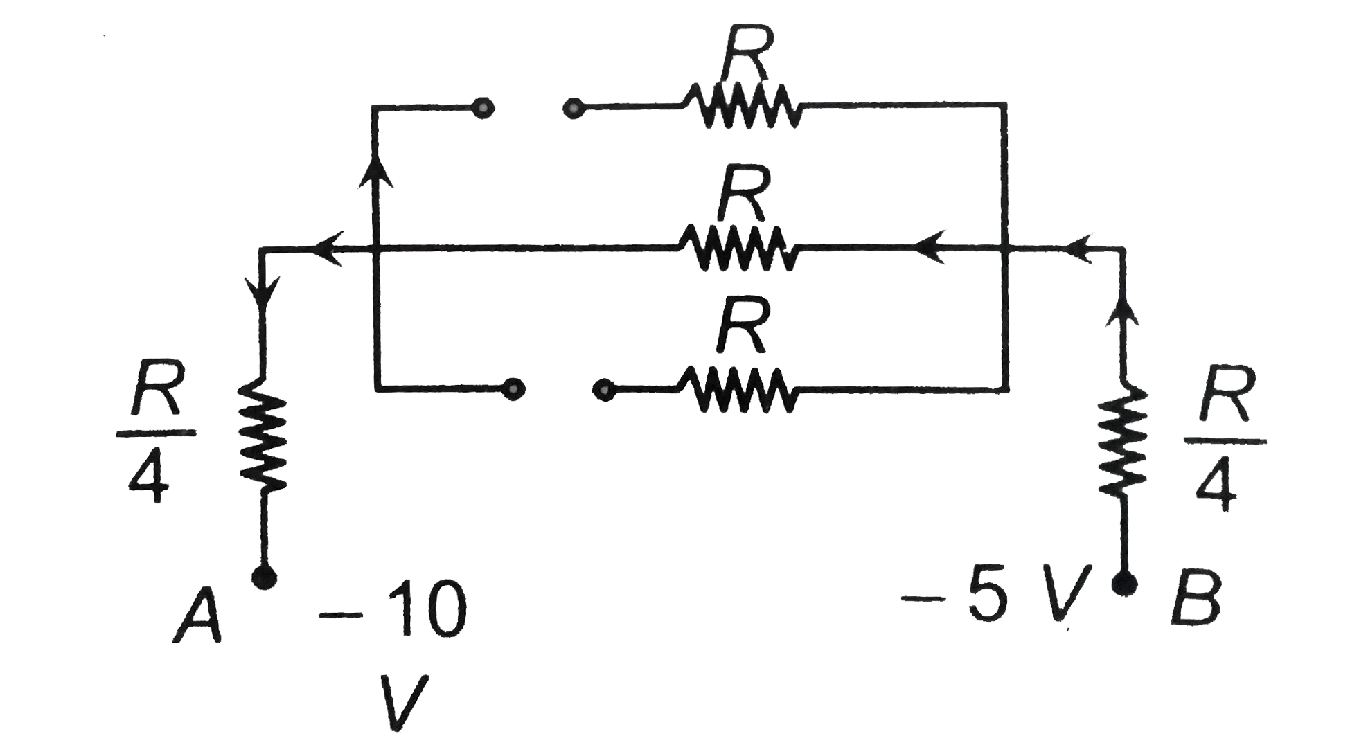
⇒RAB=R4+R2+R4=R
(ii) When VA=−5V and VB=−10V
Diodes D1 is reverse biased D1 and D3 are forward biased.
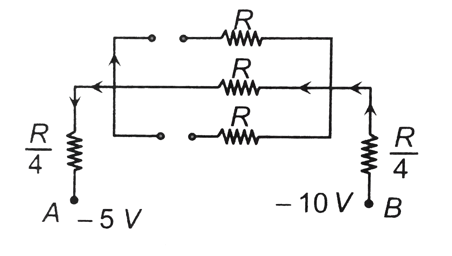
⇒R4+R2+R4=R.=R
(iii) In this case equivalent resistance between A and B is also R.
Hence (ii)=(iii)<(i).
Topper's Solved these Questions
- SEMICONDUCTOR ELECTRONICSBook:A2ZChapter:SEMICONDUCTOR ELECTRONICSExercise:Junction Transistor
Explore 47 Videos
- SEMICONDUCTOR ELECTRONICSBook:A2ZChapter:SEMICONDUCTOR ELECTRONICSExercise:Digital Electronics
Explore 40 Videos
- SEMICONDUCTOR ELECTRONICSBook:A2ZChapter:SEMICONDUCTOR ELECTRONICSExercise:Junction Diode
Explore 57 Videos
- NUCLEAR PHYSICSBook:A2ZChapter:NUCLEAR PHYSICSExercise:Section D - Chapter End Test
Explore 29 Videos
- SOURCE AND EFFECT OF MAGNETIC FIELDBook:A2ZChapter:SOURCE AND EFFECT OF MAGNETIC FIELDExercise:Section D - Chapter End Test
Explore 30 Videos
Similar Questions
Knowledge Check
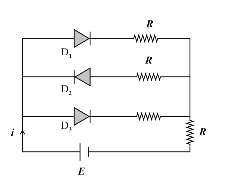
In the following circuit of PN junction diodes D1,D2 and D3 are ideal then i is
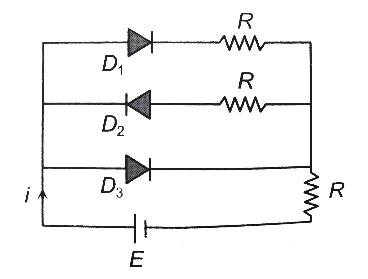 AE/RBE/2RC2E/3RDZero
VA and VB denote potential of A and B, then the equivalent resistance between A and B in the adjoining circuit is (ideal diode).
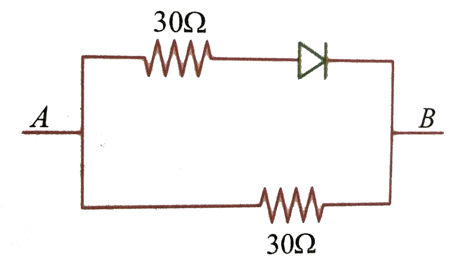 .A15ΩifVA>VBB30ΩifVA<VBCboth 1 and 2Dneither 1 nor 2
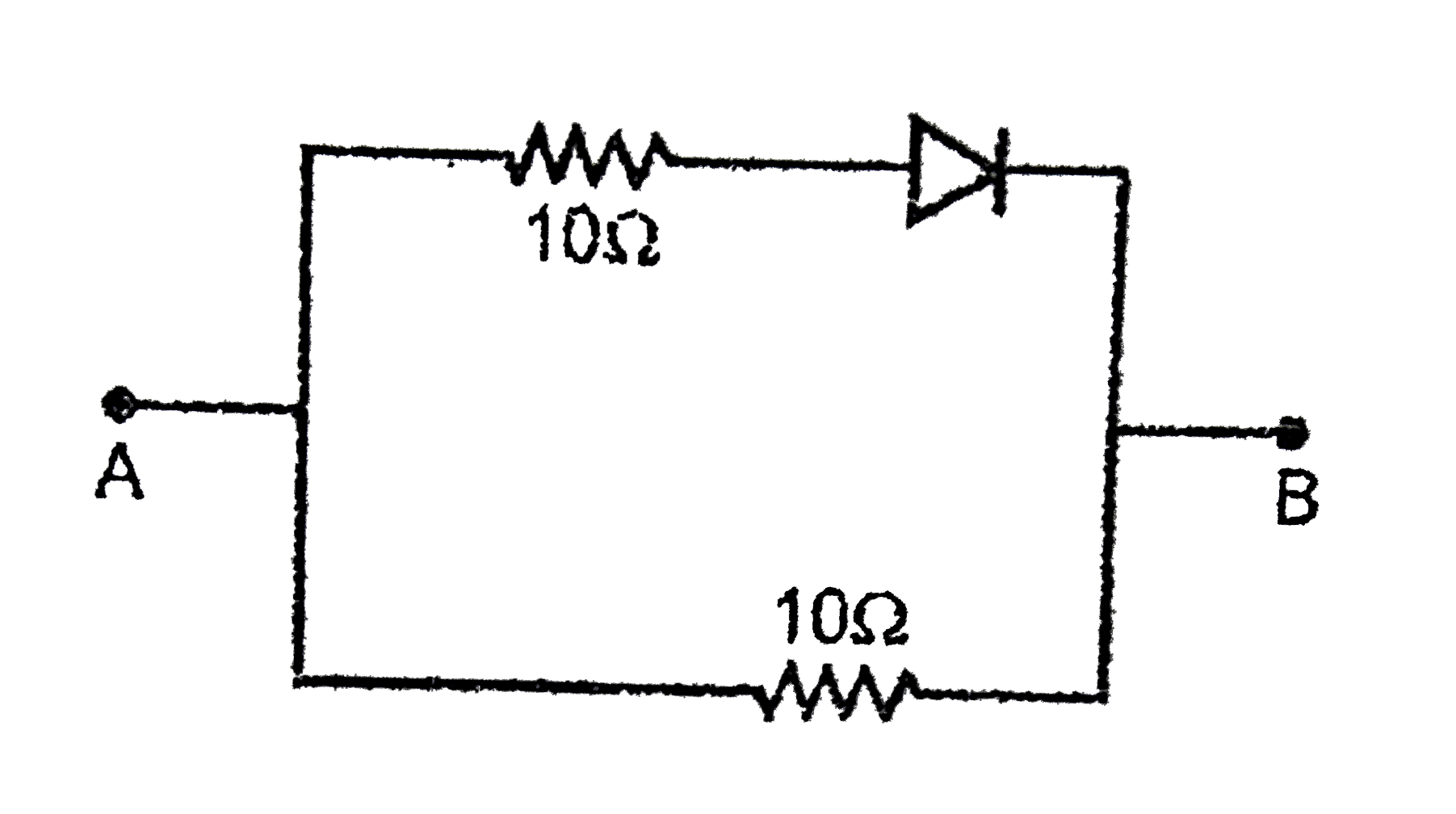
If VA and VB denote the potentials of A and B, then the equivalent resistance between A and B in the adjoint electric circuit isA10 ohm if VA>VBB5 ohm if VA<VBC5 ohm if VA>VBD20 ohm if VA>VB
VAandVB denot potentils of A and B then the equivalent resistance of A and B, then the equivalent resistance between A and B in the adjoining circuit is (ideal diode)

View SolutionTwo condensers C1 and C2 in a circuit are jhioned as shown in . The potential fo point A is V1 and that of B is V2 . The potential of point D will be

View SolutionIn the circuit shown ε1 and ε2 are two ideal sources of unknown emf. Some currents are shown in some branches of the circuit. Potential difference appearing across resistance 6Ω is VA−VB=10V. Then
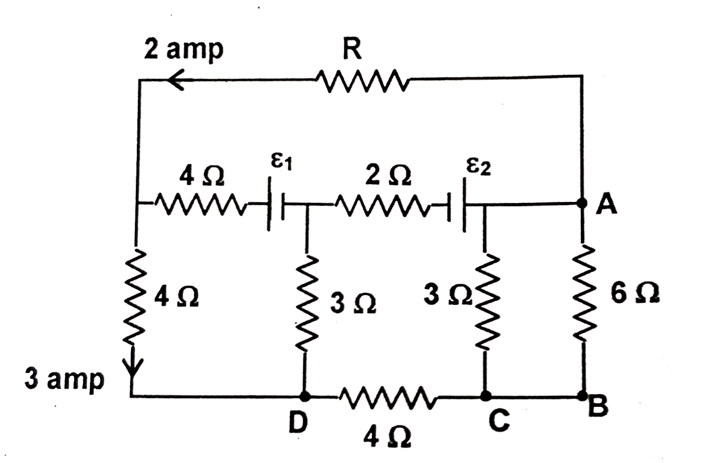
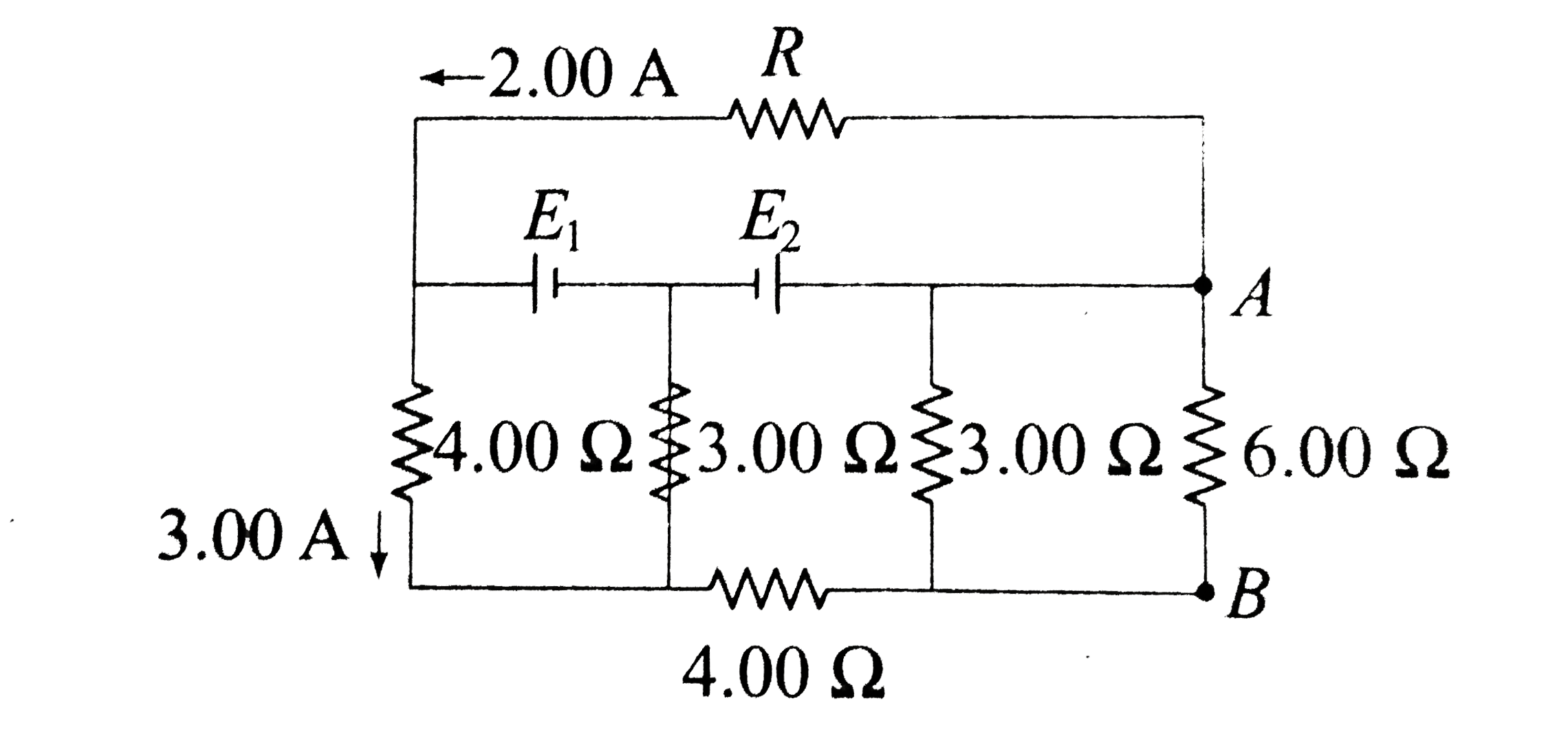
View SolutionIn the circuit shown in figure, E1andE2 are two ideal sources of unknown emfs. Some currents are shown. Potential difference appearing across 6Ω resistance is VA−VB=10V.
View SolutionTwo ideal junction diodes D1,D2 are connected as shown in the figure. A 3V battery is connected between A and B. The current supplied by the battery if its positive terminal is connected to A is
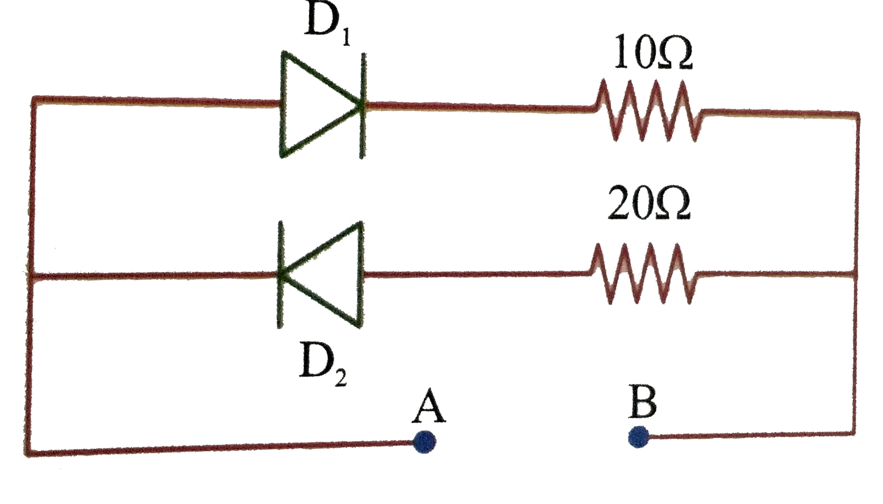 .
.
View Solution

