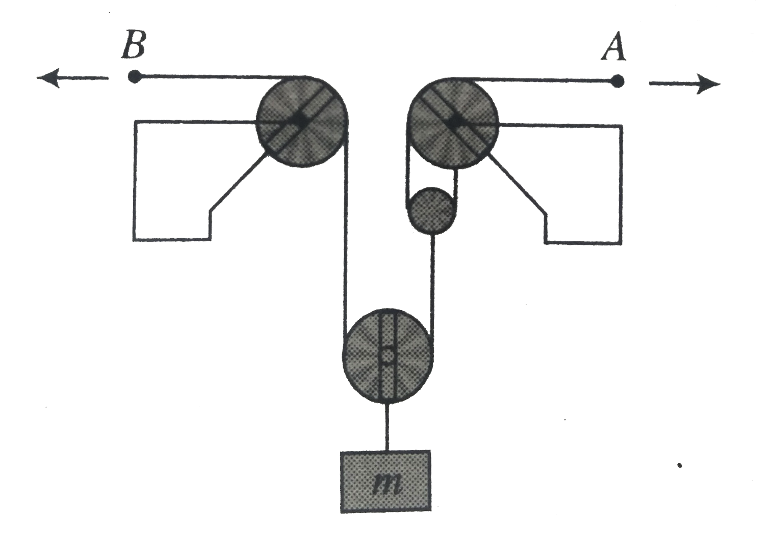
For the pulley system shown in fig. each of the cables at A and B is given a velocity of 2ms−1 in the direction of the arrow. Determine the upward velocity v of the load m.
1.5ms−1
3ms−1
6ms−1
4.5ms−1
The correct Answer is:A
VA=2ms−1 (towards right )
∴VP1=VA2=1ms−1 (upwards)
VB=2ms−1 (towards left)
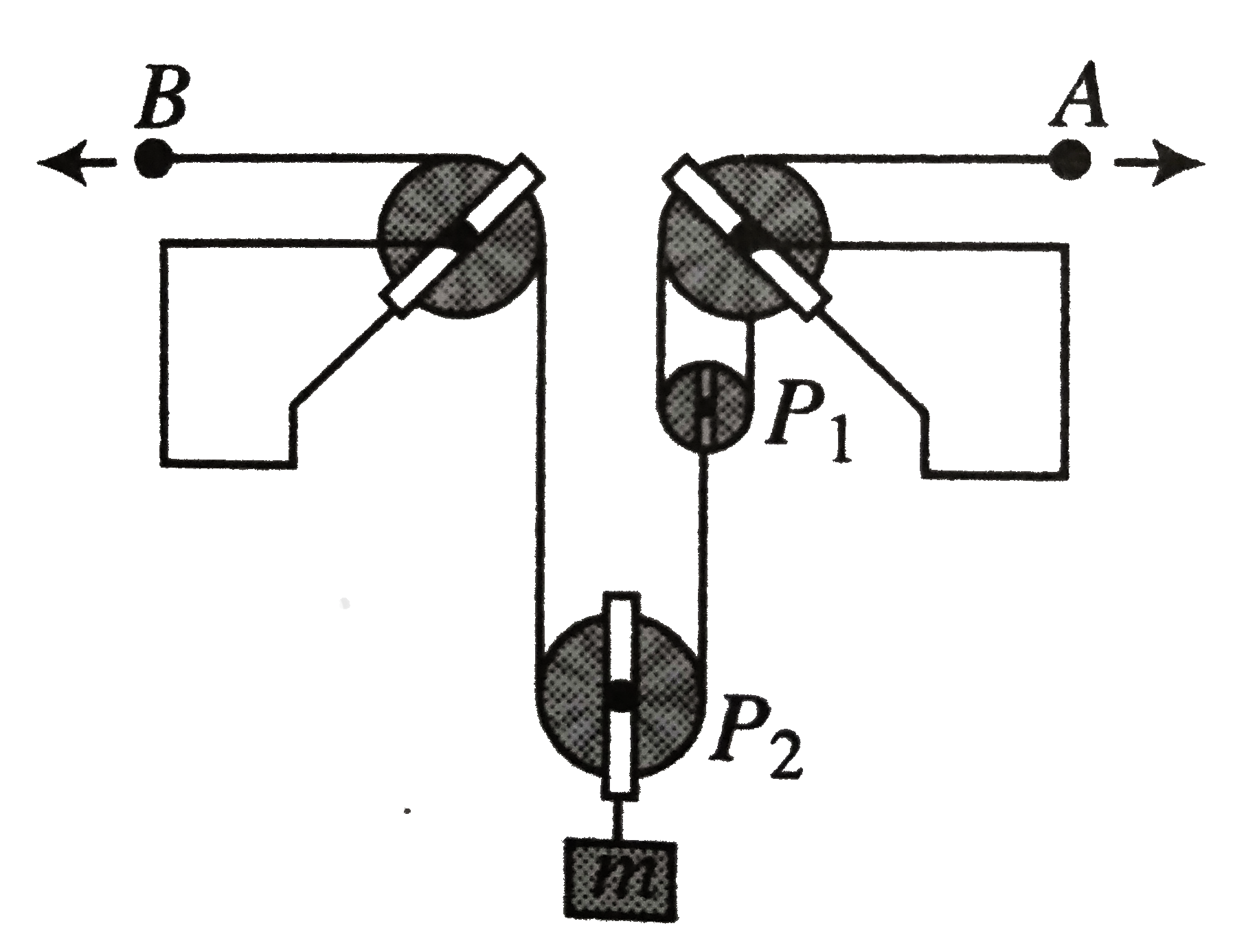
Now 2VP2=VB+VP1
∴VP2=VB+VP12=2+12=1.5ms−1.
Topper's Solved these Questions
- NEWTON'S LAWS OF MOTION 1Book:CENGAGE PHYSICSChapter:NEWTON'S LAWS OF MOTION 1Exercise:Multiple Correct
Explore 11 Videos
- NEWTON'S LAWS OF MOTION 1Book:CENGAGE PHYSICSChapter:NEWTON'S LAWS OF MOTION 1Exercise:Assertion-reasoning
Explore 15 Videos
- NEWTON'S LAWS OF MOTION 1Book:CENGAGE PHYSICSChapter:NEWTON'S LAWS OF MOTION 1Exercise:Subjective
Explore 15 Videos
- MISCELLANEOUS VOLUME 2Book:CENGAGE PHYSICSChapter:MISCELLANEOUS VOLUME 2Exercise:INTEGER_TYPE
Explore 10 Videos
- NEWTON'S LAWS OF MOTION 2Book:CENGAGE PHYSICSChapter:NEWTON'S LAWS OF MOTION 2Exercise:Integer type
Explore 1 Video
Similar Questions
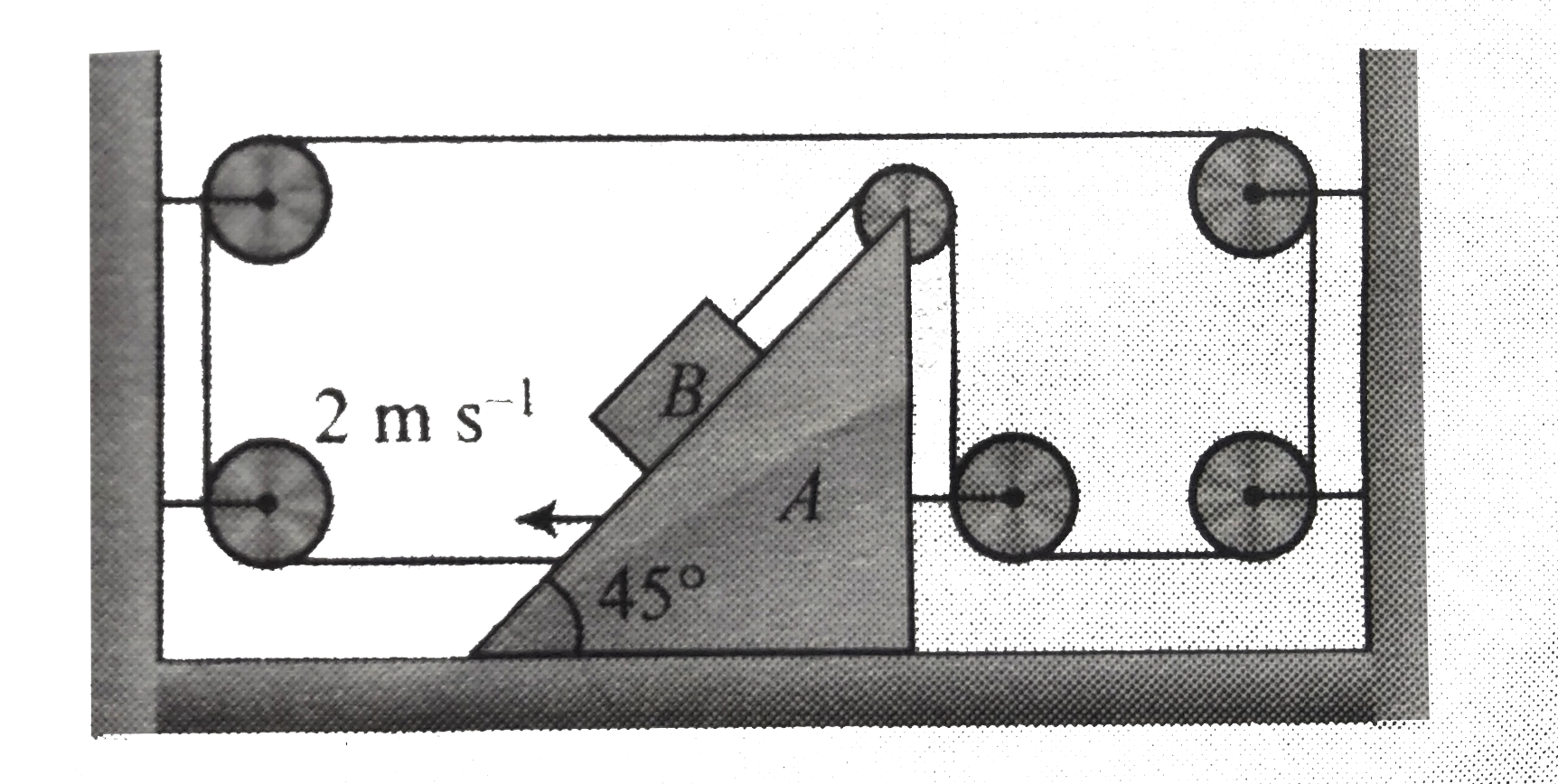
System is shown in fig. and wedge is moving toward left with speed 2ms−1. Find the velocity of the block B.
View SolutionA car A moves with velocity 15ms−1 and B with velocity 20ms−1 are moving in opposite directions as shown in . Find the relative velocity of B w.r.t. A and w.r.t. B.
 .
.
View Solution
Knowledge Check
A block A has a velocity of 0.6ms−1 the right. Determine the velocity of cylinder B.
 A1.2ms−1B2.4ms−1C1.8ms−1D3.6ms−1
The car A is used to pull a load B with the pulley arrangement shown. If A has a forwed pulley arraangement shown. If A has a forward velcotiy vA determine an experssion for the upward velcotiy vB of the load in terms of VA and θ,θ is angle between string and horizontal
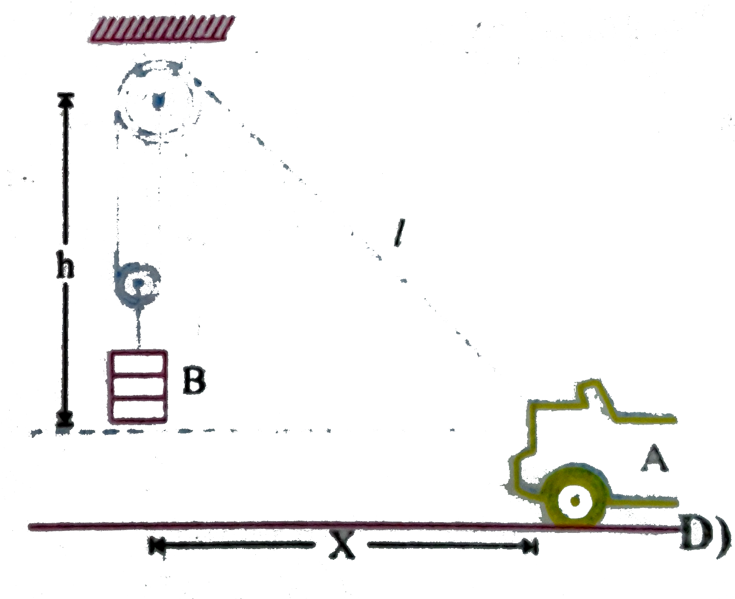 .A12VAcosθBVAsinθCVAcosθD12VAtanθ
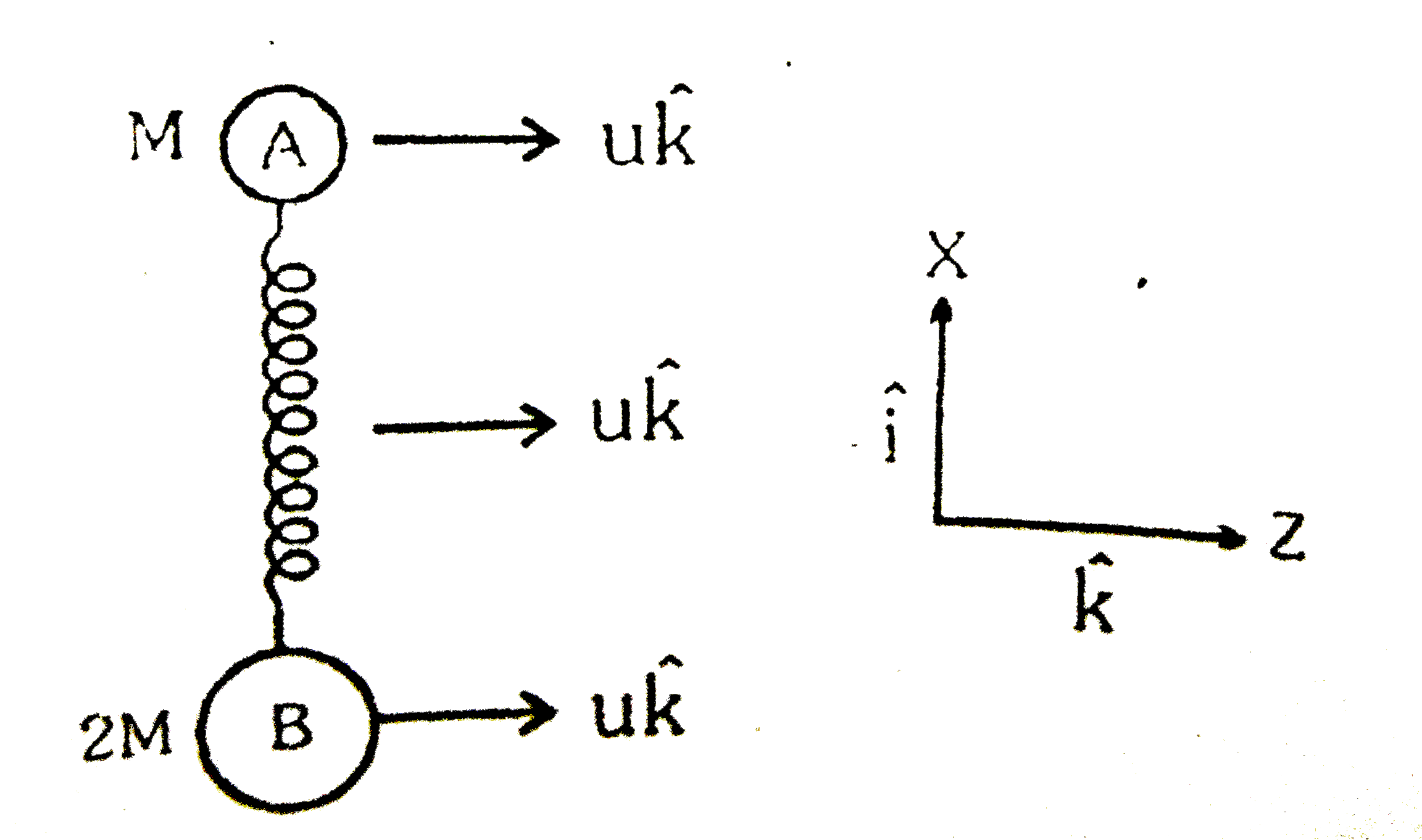
Two masses A and B of mass M and 2M respectively are connected by a compressed ideal spring. The system in placed on a horizontal frictionless table and given a velocity uˆk in the z-direction as shown in the figure. The spring is then released. In the subsequent motion the line from B to A alwyas points along the ˆi unit vector. All some instant of time mass B has a x-component of velocity as vxˆi. The velocity →vA of mass A at that instant is :-
 Avxˆi+uˆkB−vxˆi+uˆkC−2vxˆi+uˆkD2vxˆi+uˆk
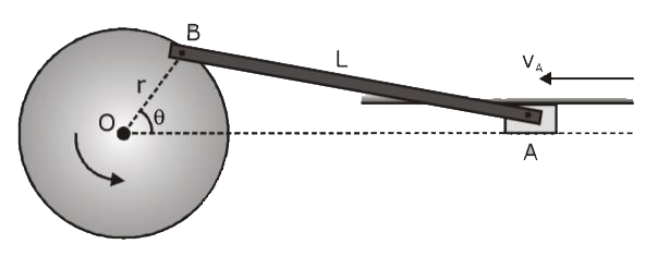
Find the velocity of point B in the crank mechanism if the velocity of point A is vA , in the direction shown. The information is given in the figure.
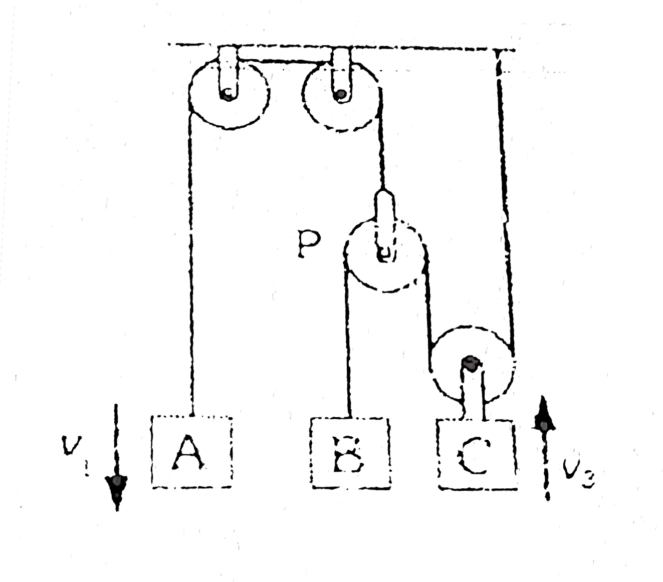
View SolutionIn the system shown, the block A is moving down eith velocity v1 and C is moving up with velocity v3. Express velocity of the block B in terms of velocities of the blocks a and C.
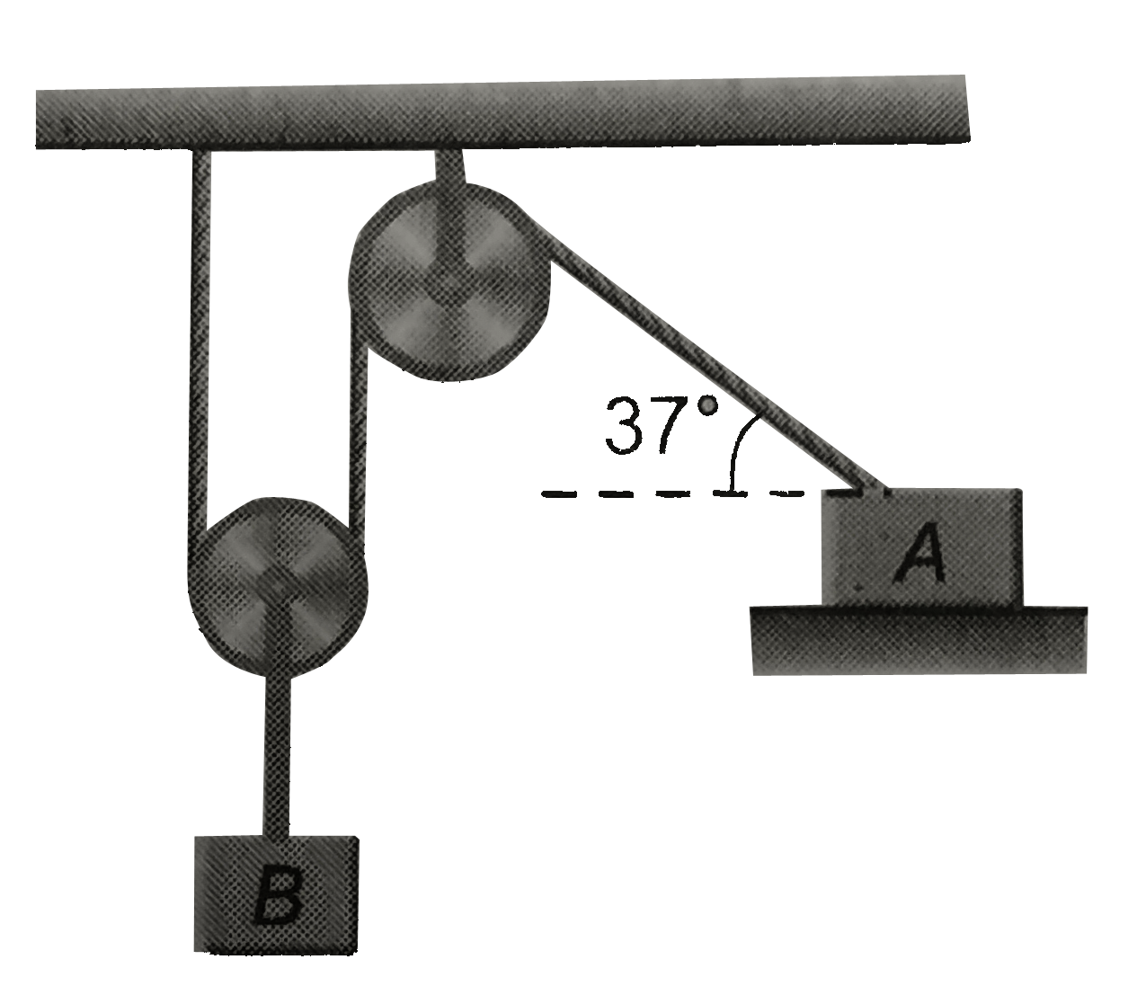
View SolutionIn the figure shown the block B moves with , velocity 10ms−1. The velocity of A in the position shown is
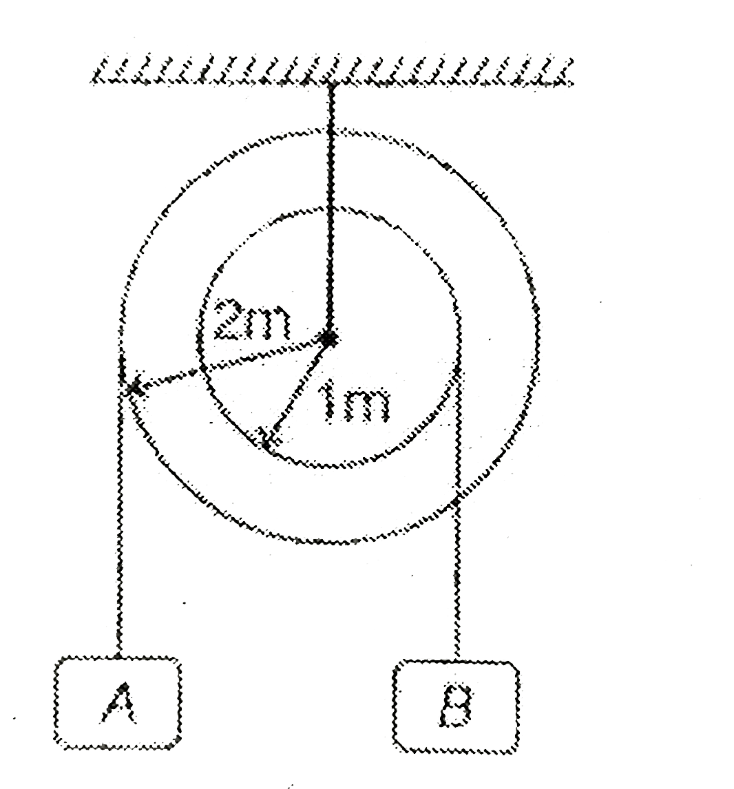
View SolutionIn the pully system shown, if radii of the bigger and smaller pulley are 2m and 1m respectively and the acceleration of block A is 5m/s2 in the downward direction, then the acceleration of block B will be
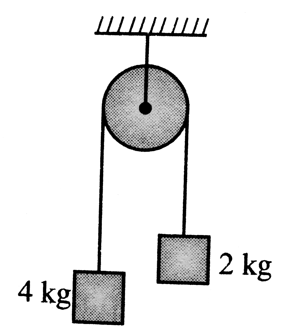
View SolutionFor the system shown in Fig. the string is light and pulley is frictionless. The 4kg block is given an upward velocity of 1m/s. The centre of mass of the two blocks will [neglect the impulse duration]
View Solution

