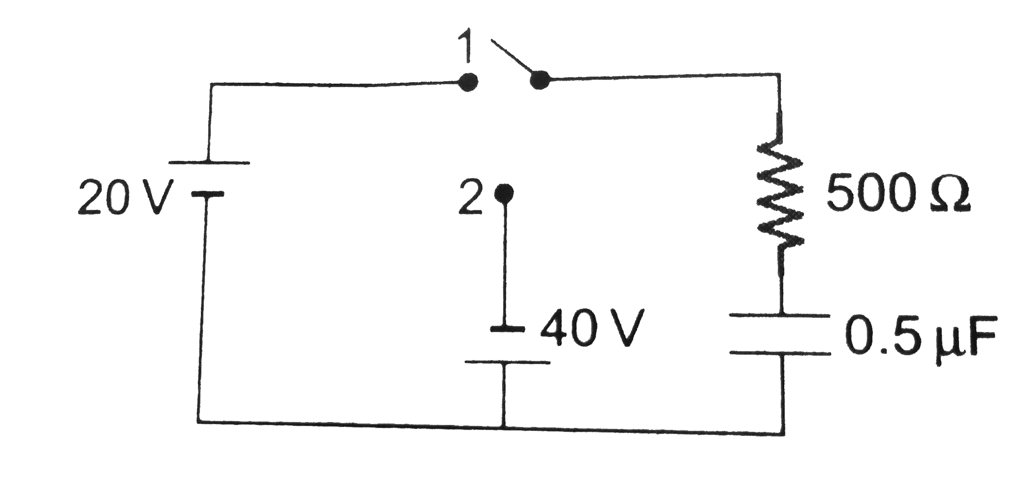
In the given circuit the switch ils closed in the positin 1 at t=0 and then moved to 2 after 250μs. Derive and expression for current as a functioin of time for t>0. Also plot the variation of current with time.
The correct Answer is:B
Time constant of the circuit is
τC=CR=(0.5×10⁻⁶)(500)=2.5×10⁻⁴s
for t≤250μsi=i0e−tτC
here ei0=20500=0.04A
∴i=(0.04e−4000t)amp
At t=250μs=2.5×10⁻⁴s
i=0.04e_1=0.015amp
At this moment PD across the capacitor
VC=20(1−e−1)=12.64V
So when the switch is shifted to positon 2, the current in the circuit is 0.015 (clockwise) and PD across capacitor is 12.64V

As soon as the switch is shifted to positio 2 current will reverse its direction with minimum current
i′0=40+12.64500
=0.11A
Now, it wil decrease exponentially to zero
For t≥250μs
i=−i′0e−tτC)=−0.11e−4000t
The (i-t) graph is as shown in figure

Topper's Solved these Questions
- CAPACITORSBOOK - DC PANDEYCHAPTER - CAPACITORSEXERCISE - OBJECTIVE_TYPE
1 Videos
- CAPACITORSBOOK - DC PANDEYCHAPTER - CAPACITORSEXERCISE - OBJECTIVE_TYPE
1 Videos
- ATOMSBOOK - DC PANDEYCHAPTER - ATOMSEXERCISE - MEDICAL ENTRANCES GALLERY
42 Videos
- COMMUNICATION SYSTEMBOOK - DC PANDEYCHAPTER - COMMUNICATION SYSTEMEXERCISE - Subjective
11 Videos
Similar Questions
In the given circuit, the switch S is closed at time t=0 then select the correct statement for current l in resistance PQ as shown in the figure
_PHY_E05_091_Q01.png)
View SolutionIn the given circuit, the switch S is closed at time t = 0, then select the correct statement for current l in resistance PQ as shown in the figure.
_PHY_E05_045_Q01.png)
View Solution
Knowledge Check
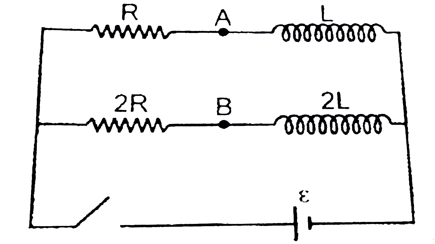
In given LR circuit the switch S is closed at time t=0 thenAThe ratio of induced emfs in the inductors of inductance L and 2L will be constantBThe ratio of induced emfs in the inductor of inductance L and 2L will be time varyingCthe potential difference VA−VB increases with timeDThe potential difference VA−VB will be constantIn the circuit shown, the switch is closed at t=0, the currents I1,I2 and I3 are
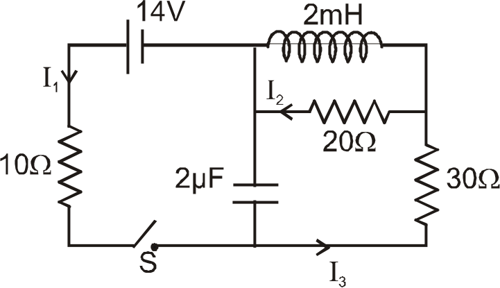 A1.4A,0,0B1.4 A,0.70 A,0.70 AC0,0,0D1.2A,0.6A,0.6A
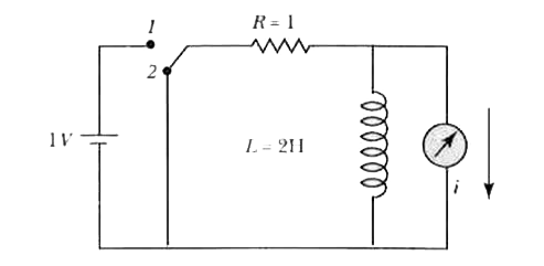
In the circuit shown in the following figure, the switch is moved to position 1 at t = 0. Which of the following most closely represents the current I as a function of time?
 A
A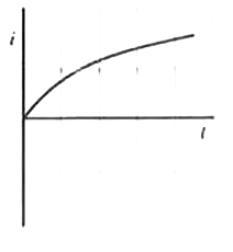 B
B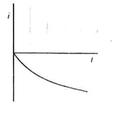 C
C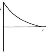 D
D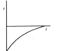
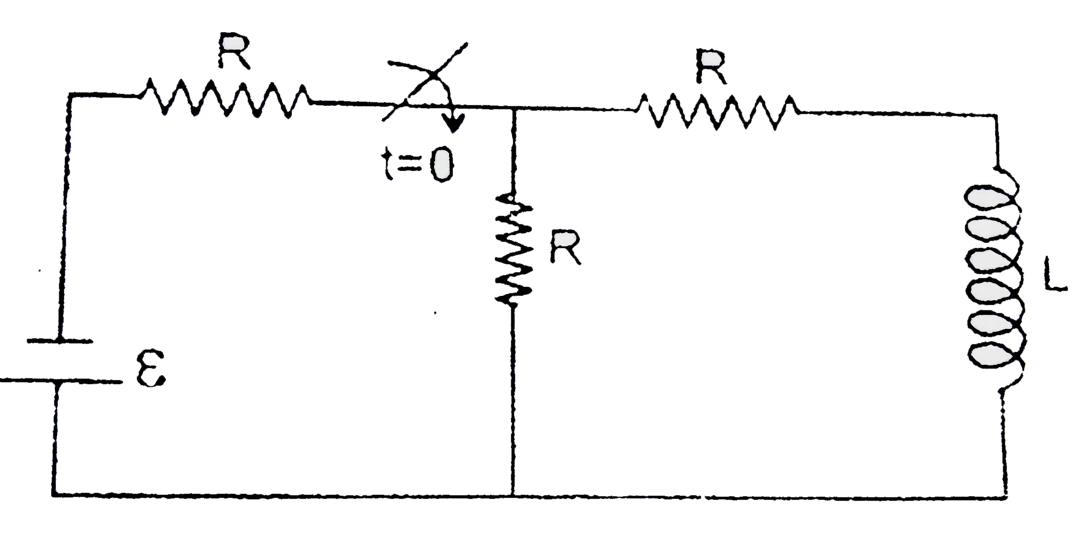
In the following circuit the switch is closed at t=0.Intially there is no current in inductor.Find out current the inductor coil as a function of time.
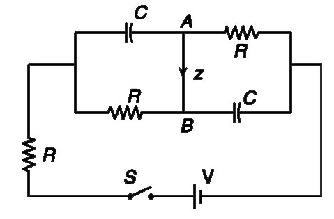
View SolutionIn the circuit shown in the fig, the switch ‘S’ is closed at time t=0. The current in branch AB is represented by z and is taken to be positive when it is from A to B.
(a) Write the value of z immediately after the switch is closed.
(b) Write the value of z infinite time after the switch is closed.
(c) Write z as a function of time (t) and plot the variation of z with time.
(d) At what time t0 the current z becomes zero ?
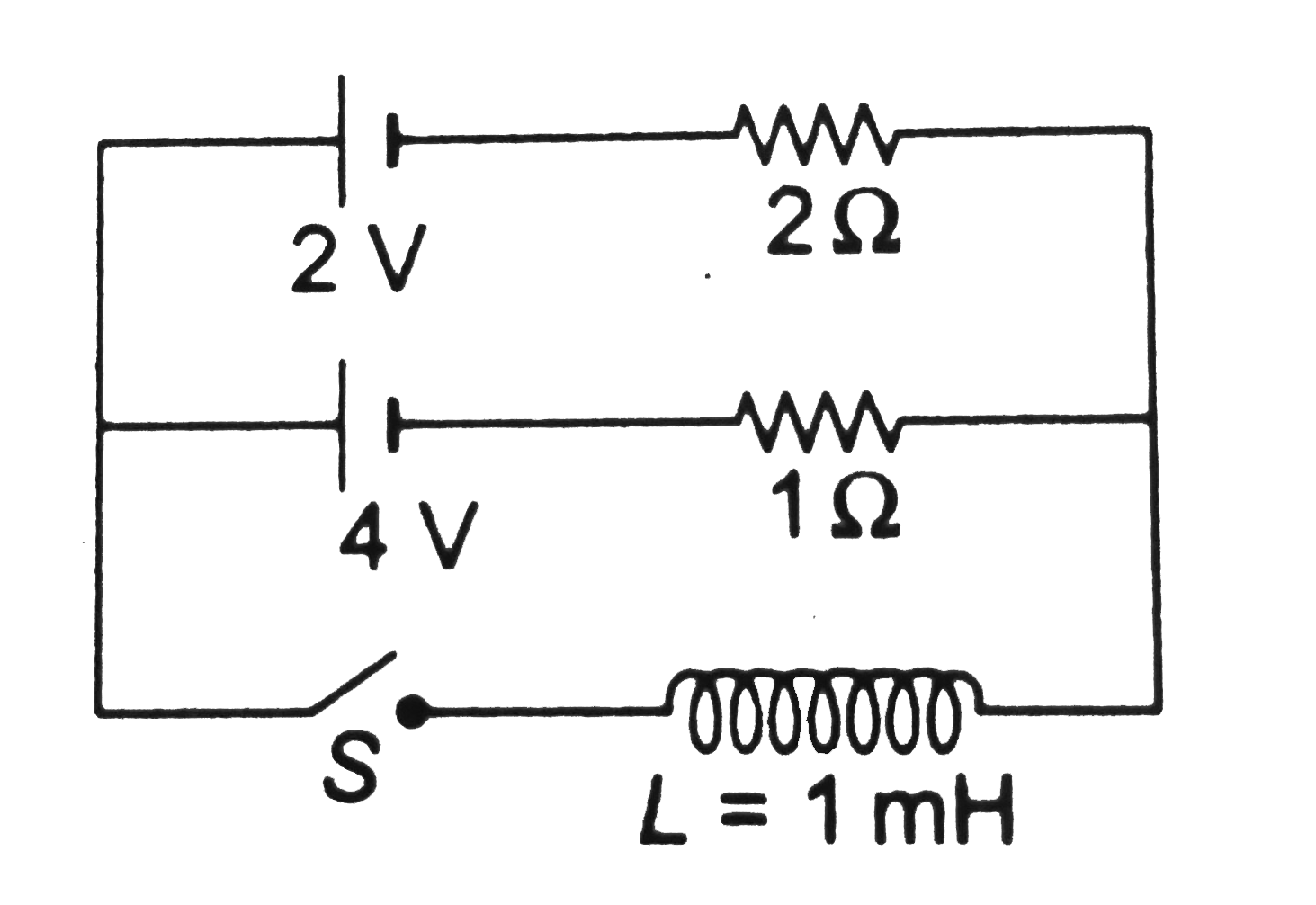
View SolutionIn the circuit shown, switch S is closed at time t=0. Find the current through the inductor as a function of time t.
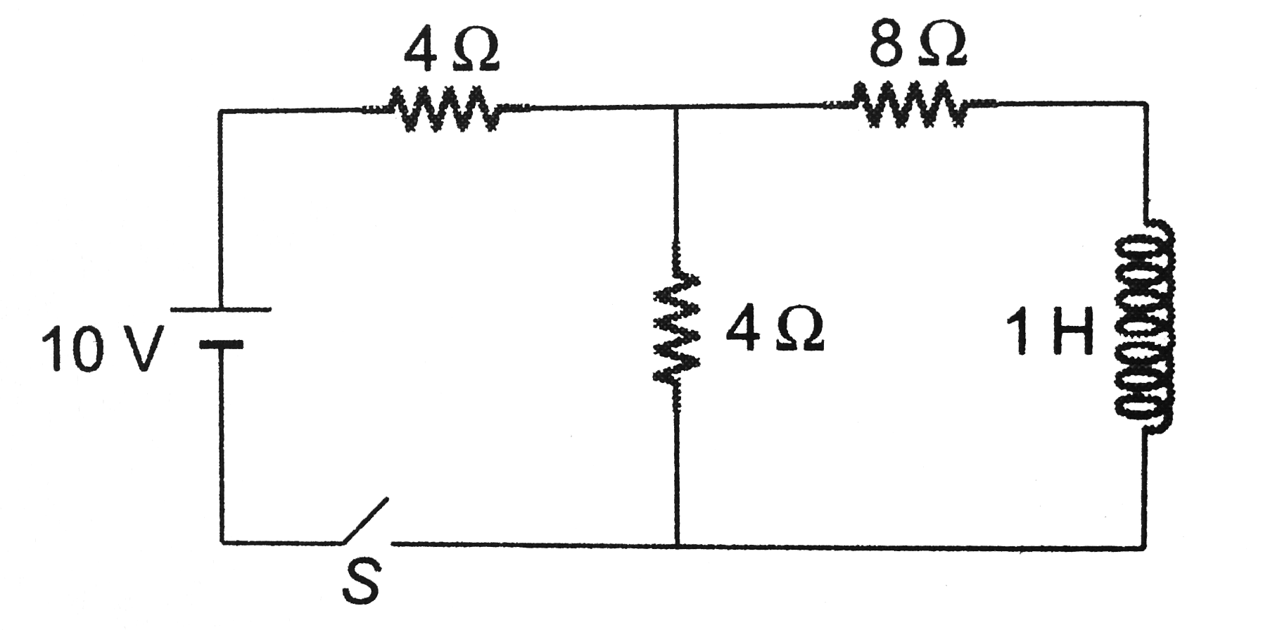
View SolutionThe switch in figure is closed at time t=0. Find the current in the inductor and the current through the switch as functions of time thereafter.
View SolutionIn the given circuit switch is closed at t=0. The charge flown in time t=Tc (where Tc is time constant).
View Solution
