Calculate the charge on each capacitor and the potential difference across it in the circuits shown in figure for the cases :
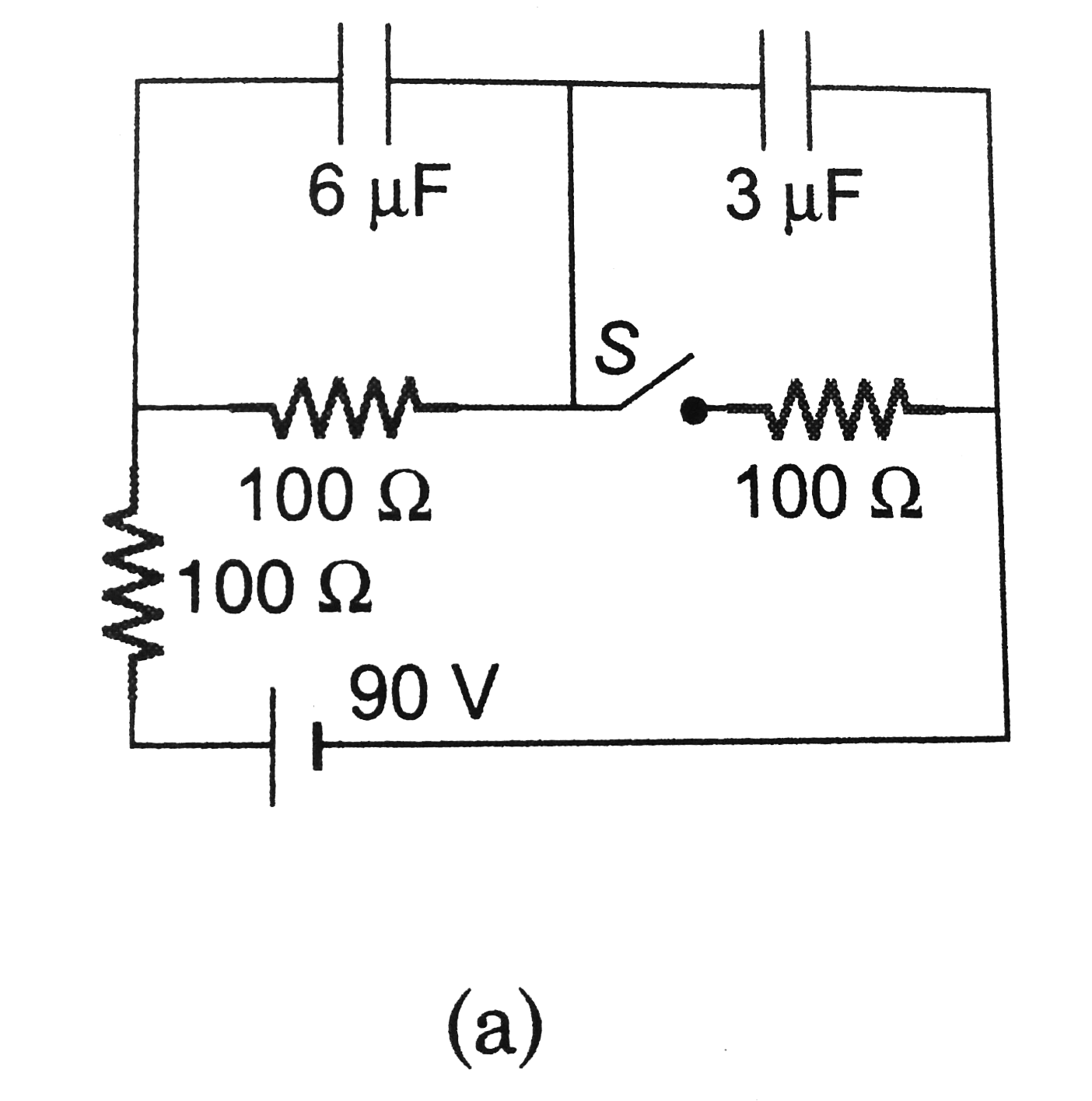
(i) switch S is closed and
(ii) switch S is open.
(iii) In. figure (b), what is the potential of point A when S is open?
Video Solution
Text Solution
The correct Answer is:A
a. Fig a. V6=903=30V,q6=6×30=180μC
V3=903=30V
q3=30×3=90μC
Fig b. Capacitor 1μF is short circuited.
Therefore q1=0
V26=(2020+20+10)×100=40V
This 40V will distribute in inverse ratio of capacity.
∴V6=28×40=10V
V2=68×40=30V
∴q6=60μC,q2=60μC
b. Fig a When S is open 6μF is short-circuited
or V6=0,q6=0
and V3=90V,q3=270μC
Fig b. When S is open V1=100V
q1=100μC
V26=100V
∴V6=28×100=25V
and V2=68×100=75V
∴q6=150μC,q2=150μC
Further, VA−0=V2
∴VA=V2=75V
|
Topper's Solved these Questions
- CAPACITORSBOOK - DC PANDEYCHAPTER - CAPACITORSEXERCISE - OBJECTIVE_TYPE
1 Videos
- CAPACITORSBOOK - DC PANDEYCHAPTER - CAPACITORSEXERCISE - OBJECTIVE_TYPE
1 Videos
- ATOMSBOOK - DC PANDEYCHAPTER - ATOMSEXERCISE - MEDICAL ENTRANCES GALLERY
42 Videos
- COMMUNICATION SYSTEMBOOK - DC PANDEYCHAPTER - COMMUNICATION SYSTEMEXERCISE - Subjective
11 Videos
Similar Questions
Knowledge Check
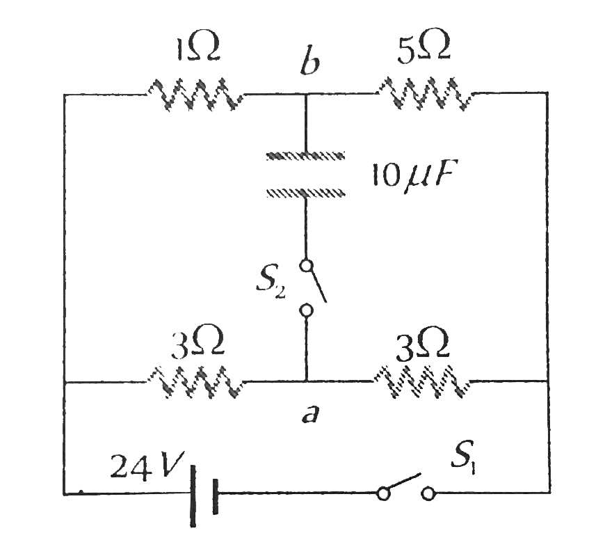
In the circuit shown in figure, switch S is initially closed and S is open. Find V-V
 A4VB8VC12VD16V
As the switch S is closed in the circuit shown in figure, current passing through it is
 A4.5AB6.0AC3.0ADZero
As the switch S is closed in the circuit shown in figure, current passed through it is.
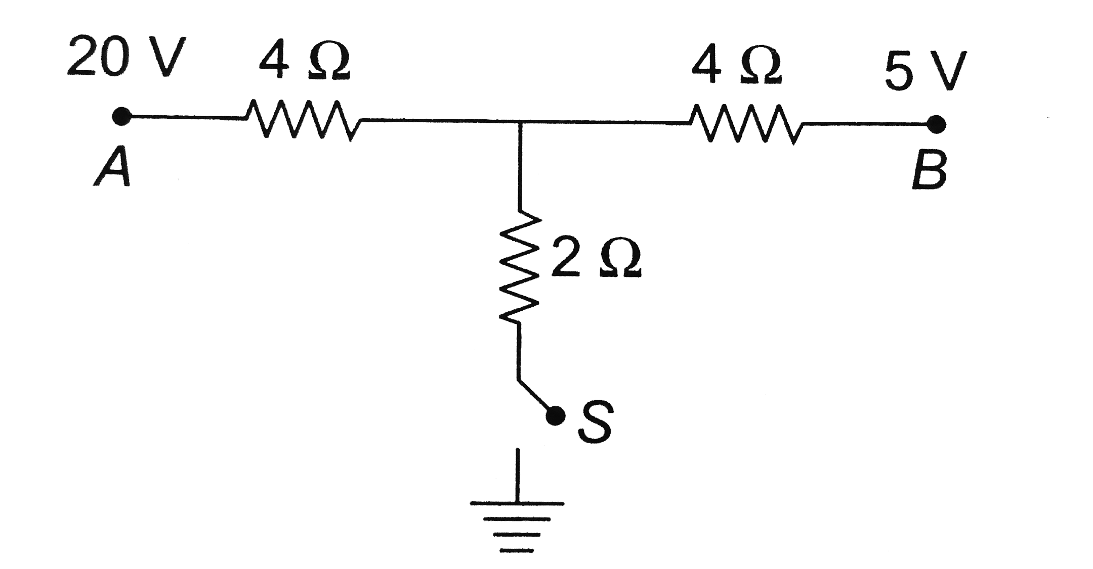 A4.5AB6.0AC3.0ADZero
Find the effective resistance of the network shown in Fig.4.15 between the points A and B when (i) the switch S is open (ii) switch S is closed.
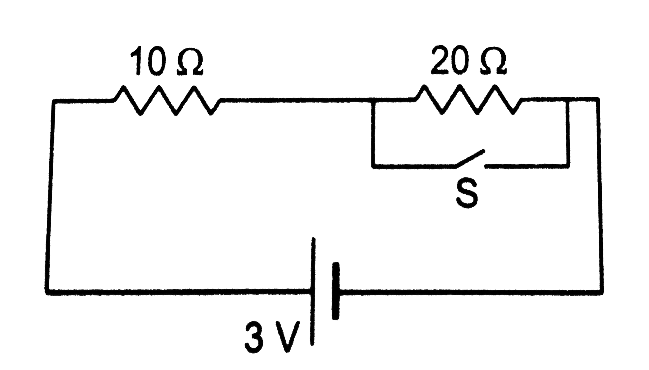
View SolutionConsider the circuit shown in figure.Find the current through the10(Ω)resistor when the switch S is (a)open (b)closed .
View SolutionIn the circuit shown in the figure, the capacitor C is charged to a potential Vo. The heat generated in the circuit when the switch S is closed, is
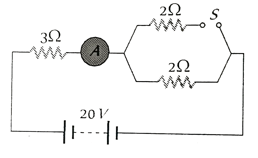
View SolutionIn the circuit shown, the reading of ammeter when switch S is open and when switch S is closed respectively are
View SolutionIn the arrangement shown in , the switch S is find
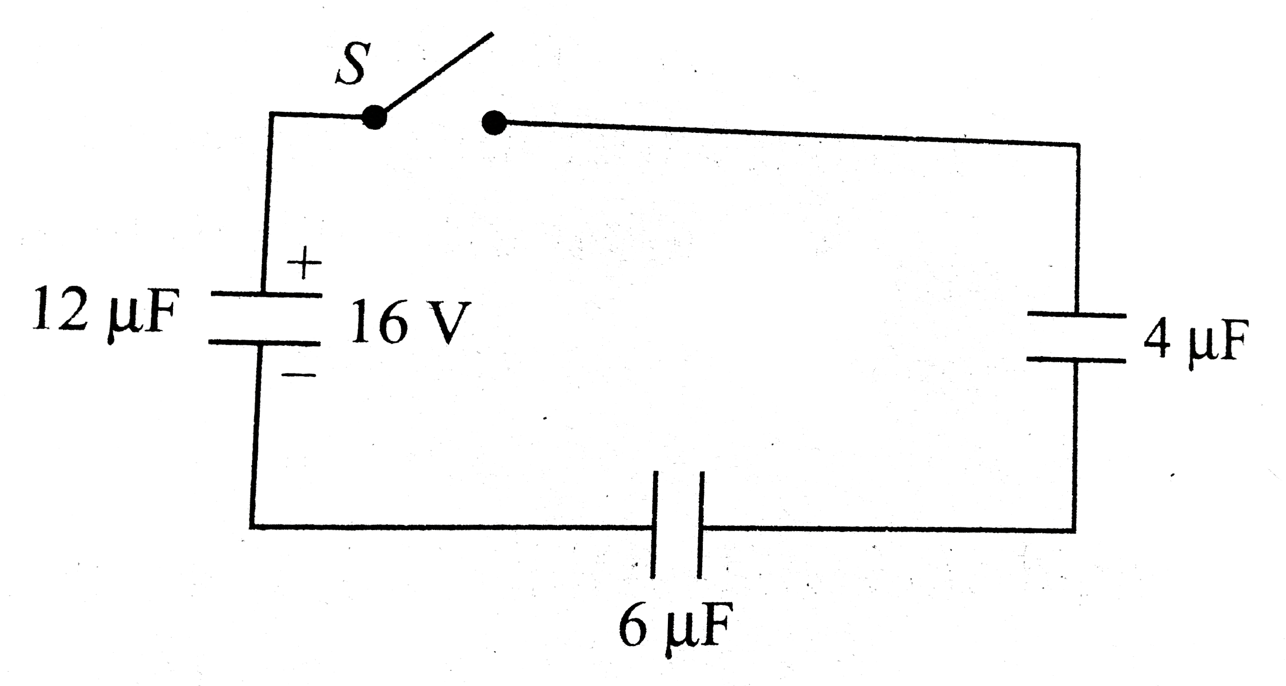 the final potential difference across the 4μF capacitor
View Solution

