Complete Solutions to MCQs of chapter ALTERNATING CURRENT of Class 12 book with complete answers and questions
| Class 12 | PHYSICS |
| Chapter | ALTERNATING CURRENT |
| NCERT FINGERTIPS | MCQs |
| Number Of Questions | 100 |
| Academic Year | 2023-24 |
Alternating voltage (V) is represented by the equation
whrere `V_(m)` is the peak voltage
View SolutionA `100 Omega` resistor is connected to a 220 V, 50 Hz ac supply.
(a) What is the rms value of current in the circuit?
(b) What is the net power consumed over a full cycle?
View SolutionThe peak voltage of an ac supply is 440 V, then its rms voltage is
View SolutionIn the question number 3, the net power consumed over a full cycle is
View SolutionThe rms value of current in an ac circuit is 25 A, then peak current is
View SolutionA alternating voltage given by `V = 140 sin 314 t` is connected across a pure resistor of 50 ohm. Find the rms current through the resistor.
View SolutionIf V=100sin (100t)V and I =100sin `(100t+(pi)/(3))` mA are the instantaneous values of voltage and current, respectively
View SolutionThe voltage over a cycle varies as
`V=V_(0)sin omega t` for `0 le t le (pi)/(omega)`
`=-V_(0)sin omega t` for `(pi)/(omega)le t le (2pi)/(omega)`
The average value of the voltage one cycle is
View SolutionThe rms value of potential difference `V` shown in the figure is
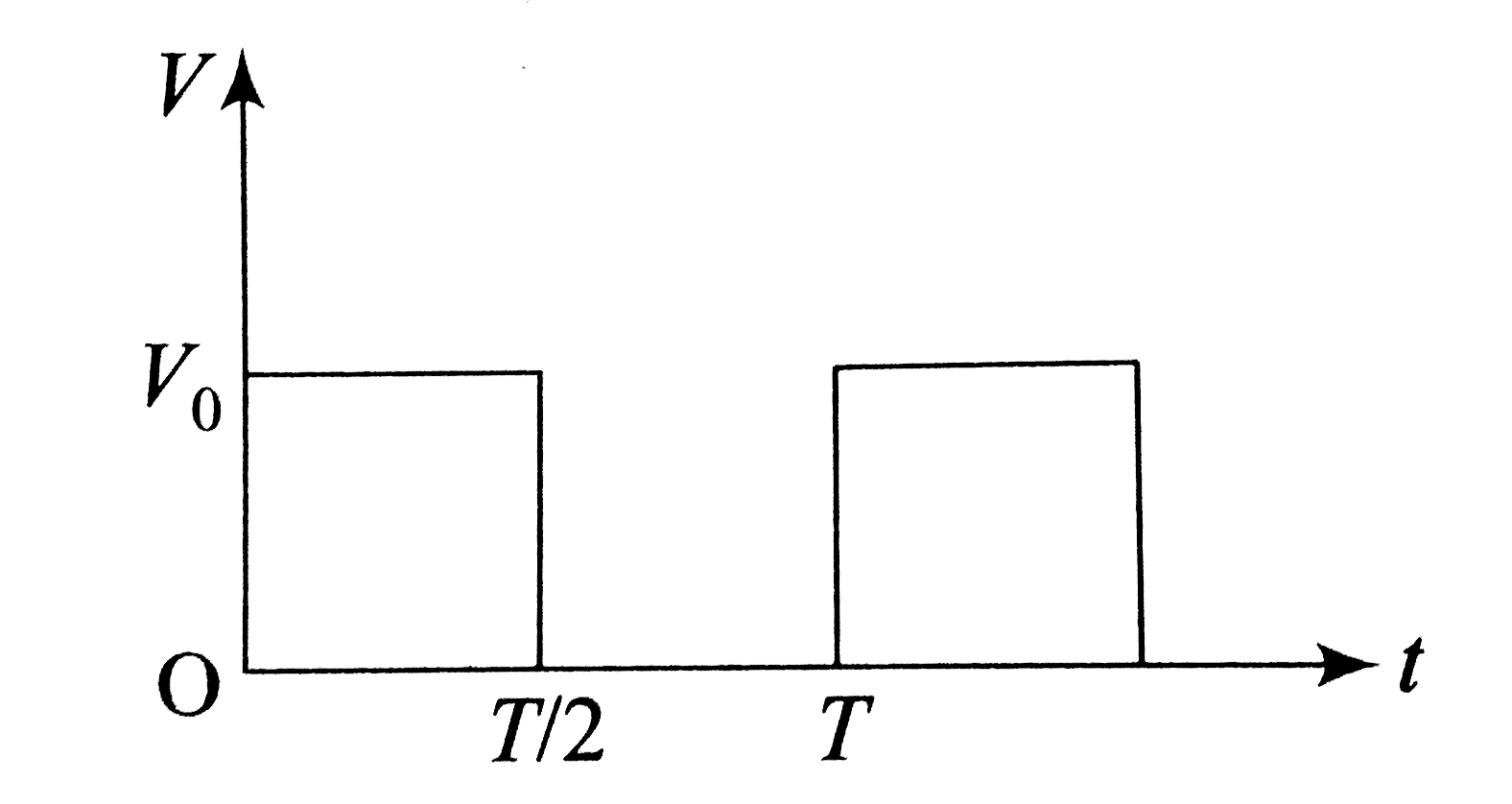
View SolutionThe relation between an ac voltage source and time in SI units is `V=120 sin(100 pi t)cos (100 pi t) V`. The value of peak voltage and frequency will be respectively
View SolutionA light bulb is rated at 100 W for a 220 V ac supply . The resistance of the bulb is
View SolutionV(rms )= 220volt , the peak voltage of the source is
View SolutionAn ac source is of `(200)/(sqrt(2))` V, 50 Hz. The value of voltage after `(1)/(600)s` from the start is
View SolutionThe line that draws power supply to your house from street has
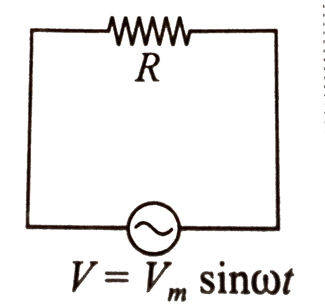
View SolutionAn ac source of voltage `V=V_(m)sin omega t` is connected across the resistance R as shown in figure. The phase relation between current and voltage for this circuit is
View SolutionThe phase relationship between current and voltage in a pure resistive circuit is best represented by
View SolutionIn an circuit, V and I are given by `V=150sin(150t) V` and `I =150sin(150t+(pi)/(3))A`. The power dissipated in the circuit is
View SolutionIn the case of an inductor
View SolutionAn ideal inductor is in turn put across 220 V, 50 Hz and 220 V, 100 Hz supplies. The current flowing through it in the two cases will be
View SolutionAn inductor of 30 mH is connected to a 220 V, 100 Hz ac source. The inductive reactance is
View SolutionWhich of the following graphs represent the correct variation of inductive reactance `X_(L)` with frequency `upsilon`?
View SolutionA 44 mH inductor is connected to 220 V, 50 Hz ac supply. The rms value of the current in the circuit is
View SolutionIn a pure capacitive circuit if the frequency of ac source is doubled, then its capacitive reactance will be
View SolutionIdentify the graph which correctly reperesents the variation of capacitive reactance `X_C` with frequency
View SolutionA `5mu F` capacitor is connected to a 200 V, 100 Hz ac source. The capacitive reactance is
View SolutionIf a capacitor of `8 mu F` is connected to a 220 V, 100 Hz ac source and the current passing through it is 65 mA, then the rms voltage across it is
View SolutionPhase difference between voltage and current in a capacitor in an ac circuit is
View SolutionIn an alternating current circuit consisting of elements in series, the current increases on increasing the frequency of supply. Which of the following elements are likely to consitute the circuit ?
View SolutionA `30 mu F` capacitor is connected to a 150 V, 60 Hz ac supply. The rms value of current in the circuit is
View SolutionA `60 mu F` capacitor is connected to a 110 V, 60 Hz a.c. supply Determine the r.m.s value of current in the circuit.
View SolutionIn the question number 30, the net power absorbed by the circuit in one complete cycle is
View SolutionIn which of following circuits the maximum power dissipation is observed?
View SolutionWhen an AC voltage of 220 V is applied to the capacitor C
View SolutionAn alternating voltage (in volts) given by `V=200sqrt(2)sin(100t)` is connected to `1 mu F` capacitor through an ideal ac ammeter in series. The reading of the ammeter and the average power consumed in the circuit shall be
View SolutionIn the circuit shown in figure, what will be the reading of the voltmeter ?

View SolutionIn the series LCR circuit shown the impedance is
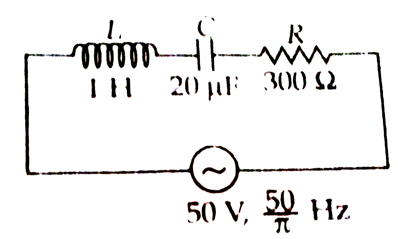
View SolutionA circuit containing a `20 Omega` resistor and `0.1 mu F` capacitor in series is connected to 320 V ac supply of angular frequency `100 " rad " s^(-1)`. The impedance of the circuit is
View SolutionA `0.2 k Omega` resistor and `15 mu F` capacitor are connected in series to a 220 V, 50 Hz ac source. The impadance of the circuit is
View SolutionAs the frequency of an ac circuit increases, the current first increases and then decreases. What combination of circuit elements is most likely to comprise the circuit ?
View SolutionA circuit consists of a resistance 10 ohm and a capacitance of `0.1 mu F` If an alternating e.m.f. of 100 V. 50 Hz is applied, calculate the current in the circuit.
View Solution200 V ac source is fed to series LCR circuit having `X_(L)=50 Omega, X_(C )=50 Omega` and `R = 25 Omega`. Potential drop across the inductor is
View SolutionA `100 mu F` capacitor in series with a `40 Omega` resistor is connected to a 100 V, 60 Hz supply. The maximum current in the circuit is
View SolutionIn the question number 42, the time lag between the current maximum and the voltage maximum is
View SolutionIn series LCR circuit, the phase angle between supply voltage and current is
View SolutionIn the question number 44, the phase difference between the voltage across the source and current is
View SolutionA sinusoidal voltage of peak value 293 V and frequency 50 Hz is applie to a series LCR circuit in which `R=6 Omega, L=25 mH` and `C=750mu F`. The impedance of the circuit is
View SolutionA pure resistive circuit element X when connected to an ac supply of peak voltage 200 V gives a peak current of 5 A which is in phase with the voltage. A second circuit element Y, when connected to the same ac supply also gives the same value of peak current but the current lags behind by `90^(@)`. If the series combination of X and Y is connected to the same suply, what will be the rms value of current?
View SolutionAn LCR series ac circuit is at resonance with 10 V each across L, C and R. If the resistance is halved, the respective voltage across L, C and R are
View SolutionIn a series LCR circuit the voltage across an inductor, capacitor and resistor are 20 V, 20 V and 40 V respectively. The phase difference between the applied voltage and the current in the circuit is
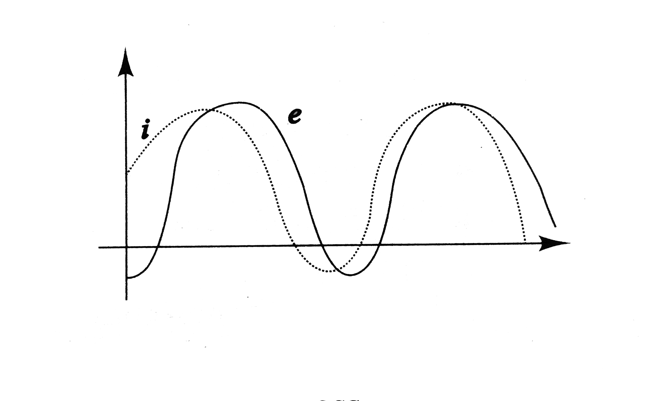
View SolutionWhen an ac source of emf`e=E_(0) sin (100 t)` is connected across a circuit, the phase difference between emf e and currnet I in the circuit is observed to be `(pi)//(4)` as shown in fig. If the circuit consists possibly only of R-C or R-C of L-R series, find the relationship find the relationship between the two elements.
View SolutionIn a circuit `L, C` and `R` are connected in series with an alternating voltage source of frequency `f`. The current lead the voltages by `45^(@)`. The value of `C` is :
View SolutionAt resonance frequency the impedance in series LCR circuit is
View SolutionAn LCR series circuit is under resonance. If `I_(m)` is current amplitude, `V_(m)` is voltage amplitude, R is the resistance, Z is the impedance, `X_(L)` is the inductive reactance and `X_(C )` is the capacitive reactance, then
View SolutionAt resonant frequency the current amplitude in series LCR circuit is
View SolutionThe resonant frequency of a series LCR circuit with `L=2.0 H,C =32 muF` and `R=10 Omega` is
View SolutionObtain the resonant frequency `(omega_(r))` of a series LCR circuit withL = 2.0 H, C = 32 `muF` and R = 10 ohm. What is the Q value of this circuit ?
View SolutionFigure shows a series LCR circuit connected to a variable frequency 230 V source.

The source frequency which drives the circuit the circuit in resonance is
View SolutionA series LCR circuit has `R=5 Omega, L=40 mH` and `C=1mu F`, the bandwidth of the circuit is
View SolutionIn LCR - circuit if resistance increases, quality factor
View SolutionIn a series LCR circuit having `L=30 mH, R=8 Omega` and the resonant frequency is 50 Hz. The quality factor of the circuit is
View SolutionA series resonant LCR circuit has a quality factor (Q-factor)=0.4. If `R=2k Omega, C=0.1 mu F` then the value of inductance is
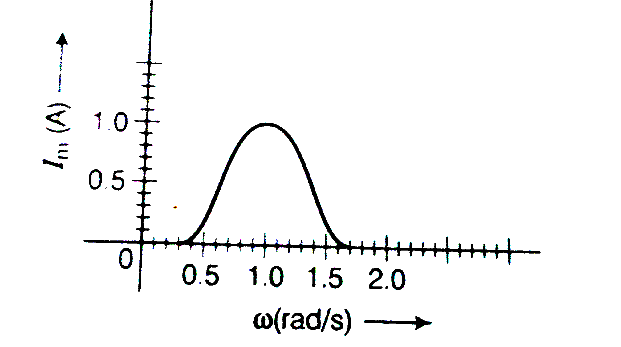
View SolutionIn series LCR circuit, the plot of `I_("max")` versus `omega` is shown in figure. Find the bandwith and mark in the figure.
View SolutionPower dissipated in an `L-C-R` series circuit connected to an `AC` source of emf `epsilon` is
View SolutionA series `LCR` circuit with `R = 20 Omega, L = 1.5 H` and `C = 35 mu F` is connected to a variable frequency `200 V` ac supply. When the frequency of the supply equals the natural frequency of the circuit, what is the average power in `kW` transferred to the circuit in one complete cycle?
View SolutionA series LCR circuit with `R=22Omega, L=1.5 H` and `C=40 mu F` is connected to a variable frequency 220 V ac supply. When the frequency of the supply equals the natural frequency of the circuit, what is the average power transferred to the circuit in one complete cycle?
View SolutionAn alternating supply of 220 V is applied across a circuit with resistance `22 Omega` and impedance `44 Omega`. The power dissipated in the circuit is
View SolutionQuality factor and power factor both have the dimensions of
View SolutionThe power factor of the circuit as shown in figure is
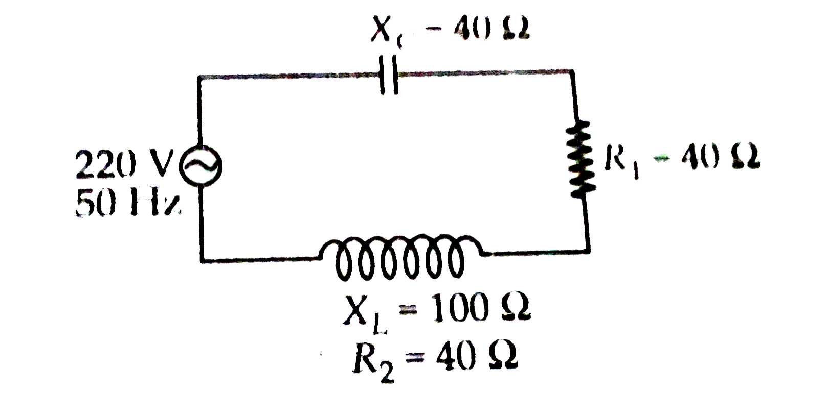
View SolutionA resistor of `500 Omega` and an inductance of 0.5 H are in series with an ac source which is given by `V=100sqrt(2)sin(1000t)`. The power factor of the combination is
View SolutionIn a series LCR circuit, the phase difference between the voltage and the current is `45^(@)`. Then the power factor will be
View SolutionFor an LCR circuit, the power transferred from the driving source to the driven oscillator is `P = I^(2) Z cos phi`.
View SolutionAn electrical device draws 2 kW power from ac mains voltage 223 V(rms). The current differs lags in phase by `phi=tan^(-1)(-(3)/(4))` as compared to valtage. The resistance R in the circuit is
View SolutionAn inductor 200 mH, capacitor `500mu F` and resistor `10 Omega` are connected in series with a 100 V variable frequency ac source. What is the frequency at which the power factor of the circuit is unity?
View SolutionIn an electrical circuit `R,L,C` and an `AC` voltage source are all connected in series. When `L` is removed from the circuit, the phase difference between the voltage and the current in the circuit is `pi//3`. If instead, `C` is removed from the circuit, difference the phase difference is again `pi//3`. The power factor of the circuit is
View SolutionA voltage of peak value 283 V and varying frequency is applied to series LCR combination in which `R=3Omega, L=25 mH` and `C=400 mu F`. Then the frequency (in Hz) of the source at which maximum power is dissipated in the above is
View SolutionThe natural frequency `(omega_(0))` of oscillations in LC circuit is given by
View SolutionA fully charged capacitor C with initial charge `q_(0)` is connected to a coil of self inductance L at t=0. The time at which the energy is stored equally between the electric and the magnetic fields is
View SolutionA charged 30 `mu F` capacitor is connected to a 27 mH inductor. What is the angular frequency of free oscillations of the circuit ?
View SolutionAn Lc circuit contains a 40 mH inductor and a `25 mu F` capacitor. The resistance of the circuit is negligible.The time is measured from the instant the circuit is closed. The energy stored in the circuit is completely magnetic at time (in milliseconds)
View SolutionAn LC circuit contains a 20 mH inductor and a `50 mu F` capacitor with an initial charge of 10 mC. The resistance of the circuit is negligible. Let the instant at which the circuit which is closed be t=0. At what time the energy stored is completely magnetic ?
View SolutionAn LC circuit contains a 20 mH inductor and `25 mu F` capacitor with an initial charge of 5 mC. The total energy stored in the circuit initially is
View SolutionA `1.5 mu F` capacitor is charged of 60 V. The charging battery is then disconnected and a 15 mH coil is connected in series with the capacitor so that LC oscillations occur. Assuming that the circuit contains no resistance, the maximum current in this coil shall be close to
View SolutionA condenser of capacity `C` is charged to a potential difference of `V_(1)`. The plates of the condenser are then connected to an ideal inductor of inductance `L`. The current through the inductor when the potential difference across the condenser reduces to `V_(2)` is
View SolutionWhat is the mechanical equivalent of spring constant k in LC oscillating circuit?
View SolutionA transformer works on the principle of
View SolutionTransformer is used to
View SolutionFor an ideal step-down transformer, the quantity which is constant for both the coils is
View SolutionQuantity that remains unchanged in a transformer is
View SolutionThe core of a transformer is laminated to reduce
View SolutionThe loss of energy in the form of heat in the iron core of a transformer is
View SolutionIn a transformer the transformation ratio is 0.3. If 220 V ac is fed to the primary, then the voltage across the secondary is
View SolutionA transformer is used to light a 140 W, 24 V lamp from 240 V AC mains. The current in mains cable is 0.7 A, find the efficiency of transformer.
View Solutionin a step-up transformer, the turn ratio is `1:2` leclanche cell (e.m.f. 1.5V) is connected across the primary. The voltage devloped in the secondary would be
View SolutionA transformer has `100` turns in the primary coil and carries `8A` current. If input power is one kilowatt, the number of turns required in the secondary coil to have `500V` output will be
View SolutionA 60 W load is connected to the secondary of a transformer whose primary draws line voltage. If a current of 0.54 A flows in the load, what is the current in the primary coil? Comment on the types of transformer being used.
View SolutionA step down transformer converts transmission line voltage from 11000 V to 220 V. The primary of the transformer has 6000 turns and efficiency of the transformer is 60%. If the output power is 9 kW, then the input power will be
View SolutionIn the question number 96, the number of turns in the secondary is
View SolutionA power transmission line feeds input power at 2400 V to a step down transformer with its primary windings having 4000 turns. What should be the number of turns in the secondary windings in order to get output power at 240 V?
View SolutionCalculate current drawn by primary coil of a transformer, Which steps down 200 V to 20 V to operate a device of 20 ohm resistance. Assume efficiency of transformer 80 %.
View SolutionA small town with a demand of 800 kW of electric power at 220 V is situated 15 km away from an electric plant generating power at 440 V. The resistance of the two line wires carrying power is `0.5 Omega` per km. The town gets power from the lines through a 4000-220 V step down transformer at a substation in the town.
Estimate the line power loss in the form of heat.
(b) How much power must the plant supply. assuming there is negligible power loss due to leakage?
(c) Characterize the step up transformer at the plant.
View Solution
MCQs questions and complete solutions for chapter ALTERNATING CURRENT of MTG PHYSICS (ENGLISH) of Class 12