Plot a graph showing the variation of photoelectric current with anode potential for two light beam of same wavelength but different intensity.
To plot a graph showing the variation of photoelectric current with anode potential for two light beams of the same wavelength but different intensities, we will follow these steps:
1. Understand the Variables:
- The x-axis will represent the anode potential (V), and the y-axis will represent the photoelectric current (I).
- We have two light beams (let's call them A and B) with the same wavelength but different intensities.
2. Draw the Axes:
- Draw a horizontal line for the x-axis (anode potential) and label it "Anode Potential (V)".
- Draw a vertical line for the y-axis (photoelectric current) and label it "Photoelectric Current (I)".
3. Identify the Stopping Potential:
- For both light beams, since they have the same wavelength, the stopping potential (V0) will be the same. This is because the energy of the photons is determined by their frequency, which is the same for both beams.
4. Plot the Graph for Beam A:
- Start from the negative side of the x-axis where the photoelectric current is zero. As the anode potential increases (becomes less negative), the photoelectric current will start to increase.
- Initially, the current will rise gradually until it reaches a saturation current (maximum current) at a certain positive potential. Label this curve as "A".
5. Plot the Graph for Beam B:
- For beam B, which has a higher intensity, the photoelectric current will also start from zero and increase with the anode potential.
- However, due to the higher intensity, the saturation current will be greater than that of beam A. Therefore, the curve for beam B will rise to a higher saturation current than beam A. Label this curve as "B".
6. Mark the Saturation Currents:
- Indicate the saturation current levels for both beams on the y-axis. The saturation current for beam A will be lower than that for beam B.
7. Label the Stopping Potential:
- Mark the stopping potential (V0) on the x-axis for both curves, which will be the same for both beams.
Final Graph:
- The graph will show two curves starting from the origin (0,0), with curve A reaching a lower saturation current than curve B, both having the same stopping potential.
- The x-axis will represent the anode potential (V), and the y-axis will represent the photoelectric current (I).
- We have two light beams (let's call them A and B) with the same wavelength but different intensities.
- Draw a horizontal line for the x-axis (anode potential) and label it "Anode Potential (V)".
- Draw a vertical line for the y-axis (photoelectric current) and label it "Photoelectric Current (I)".
- For both light beams, since they have the same wavelength, the stopping potential (V0) will be the same. This is because the energy of the photons is determined by their frequency, which is the same for both beams.
- Start from the negative side of the x-axis where the photoelectric current is zero. As the anode potential increases (becomes less negative), the photoelectric current will start to increase.
- Initially, the current will rise gradually until it reaches a saturation current (maximum current) at a certain positive potential. Label this curve as "A".
- For beam B, which has a higher intensity, the photoelectric current will also start from zero and increase with the anode potential.
- However, due to the higher intensity, the saturation current will be greater than that of beam A. Therefore, the curve for beam B will rise to a higher saturation current than beam A. Label this curve as "B".
- Indicate the saturation current levels for both beams on the y-axis. The saturation current for beam A will be lower than that for beam B.
- Mark the stopping potential (V0) on the x-axis for both curves, which will be the same for both beams.
- The graph will show two curves starting from the origin (0,0), with curve A reaching a lower saturation current than curve B, both having the same stopping potential.
Topper's Solved these Questions
- BOOK - PRADEEPCHAPTER - DUAL NATURE OF RADIATION AND MATTEREXERCISE - NCERT Exerciese question1videos
DUAL NATURE OF RADIATION AND MATTER
- BOOK - PRADEEPCHAPTER - DUAL NATURE OF RADIATION AND MATTEREXERCISE - Short answer1videos
DUAL NATURE OF RADIATION AND MATTER
- BOOK - PRADEEPCHAPTER - CURRENT ELECTRICITYEXERCISE - Problems for Practice (B)2videos
CURRENT ELECTRICITY
- BOOK - PRADEEPCHAPTER - ELECTROMAGNETIC INDUCTION & ALTERNATING CURRENTEXERCISE - Multiple Choice Questions1videos
ELECTROMAGNETIC INDUCTION & ALTERNATING CURRENT
Similar Questions
Draw suitable graphs to show the variation of photoelectric current with collector plate potential for
(i) a fixed frequency but different intensities I1>I2>I3 of radiation.
(ii) a fixed intensity but different frequencies v1>v2>v3 of radiation.View SolutionDarw graphs showing variation of photoelctric current with applied voltage for two incident radiations of equal frequecny and different intensities. Mark the graph for the radiaiton of higher intensity.
View Solution
Knowledge Check
- Question 1 - Select One
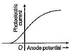
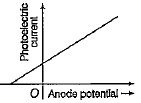
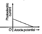
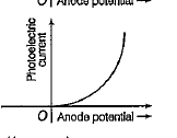
Variation of photeoelectric current with anode potential is shown below. Choose the correct option.
A B
B C
C D
D
Darw graphs showing variation of photoelctric current with applied voltage for two incident radiations of equal frequecny and different intensities. Mark the graph for the radiaiton of higher intensity.
View SolutionDraw graphs showing variation of photoelectric current with applied voltage for three incident radiations of equal frequency and different intensities. Mark the graph for the radiation of higher intensity.
View SolutionDraw a plot showing the variation of photoelectric current with collector plate potential for two different frequencies, v1>v2 of incident radiation having the same intensity. In which case will the stopping potential be higher? Justify your answer.
View SolutionDraw a plot showing the variation of photoelectric current with collector plate potential for two different frequencies, v1>v2, of incident radiation having the same intensity. In which case will the stopping potential be higher ? Justify your answer.
View SolutionPlot a graph showing variation of current versus voltage for the material GaAs
View SolutionDraw a plot showing the variation of photoelectric current with collector plate potential for two different frequenciesv1andv2(v1>v2) of incident radiation having the same intensity. In which case will the stopping potential be higher? Justify your answer.
View SolutionPlot a graph showing variation of current versus voltage for the material Ga.
View Solution
