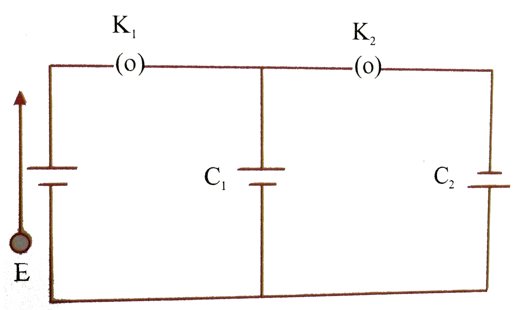
In the ciruit shown in figure, Initially K1 is closed and K2 is open, let charge on capacitor C2 is Q2 Then K1 was opened while K2 kept closed, let charge on capacitor C2 is Q2 (Take, C=1μF ) Then ratio Q2Q1 is

1:1
2:1
3:1
1:3
The correct Answer is:B
Step by step video & image solution for In the ciruit shown in figure, Initially K_1 is closed and K_2 is open, let charge on capacitor C_2 is Q_2 Then K_1 was opened while K_2 kept closed, let charge on capacitor C_2 is Q_2 (Take, C=1muF ) Then ratio Q_2/Q_1 is by Physics experts to help you in doubts & scoring excellent marks in Class 12 exams.
Topper's Solved these Questions
- BOOK - AAKASH SERIESCHAPTER - CAPACITORS EXERCISE - PRACTICE SHEET (ADVANCED) (Linked Comprehension Type Questions Passage)1videos
CAPACITORS
- BOOK - AAKASH SERIESCHAPTER - CAPACITORS EXERCISE - PRACTICE SHEET (ADVANCED) (Integer Type Questions)2videos
CAPACITORS
- BOOK - AAKASH SERIESCHAPTER - CAPACITORS EXERCISE - ADDITIONAL PRACTICE EXERCISE (LEVEL - II LECTURE SHEET (ADVANCED))(Integer Type Questions )3videos
CAPACITORS
- BOOK - AAKASH SERIESCHAPTER - ATOMSEXERCISE - PRACTICE EXERCISE21videos
ATOMS
- BOOK - AAKASH SERIESCHAPTER - COMMUNICATION SYSTEM EXERCISE - LECTURE SHEET (LEVEL - I) (MAIN) (EXERCISE - IV) (Straight Objective & More than one Correct Answer Type Questions)20videos
COMMUNICATION SYSTEM
Similar Questions
In the circuit shown in Fig, initially K1 is closed and K2 is open . What are the charges on each capacitor.
Then K1 was opened and K2 was closed (order is important). What will be the charge on each capacitor now ? [C=1μF]View SolutionIn the circuit shown in figure , initially key K1 is closed and key K2 is open. Then K1 is opened and K2 is closed (order is important). [Take Q′1 and Q′2 as charges on C1 and C2 and V1 and V2 as voltage respectively].
ThenView SolutionIn the circuit shown in figure , initially key K1 is closed and key K2 is open. Then K1 is opened and K2 is closed (order is important). [Take Q′1 and Q′2 as charges on C1 and C2 and V1 and V2 as voltage respectively].

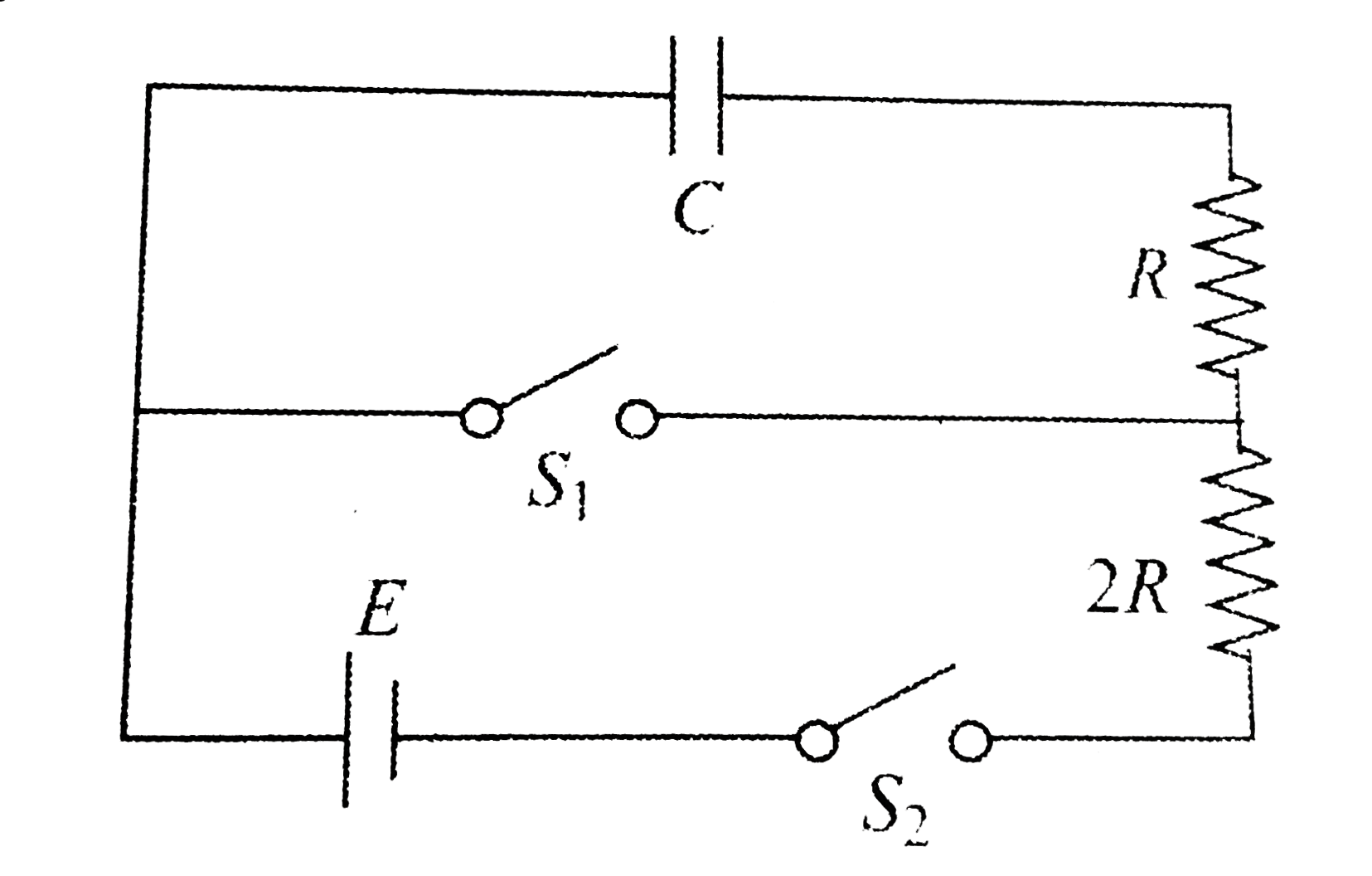
ThenView SolutionThe given R-C circuit has two swithes S1andS2 Swithc S2 is clsoed and S1 is open till the capacitor is fully charged to q0 the S2 is opened and S1 is closed simultaneously till the charge on capacitor remains q0/2 for which it takes time t1. Now S1 is again opened, and S2 is closed till chrage on capacitor becomes 3q04. it takes time t2 (see fig for referecne). Find the raito t1/t2
 View Solution
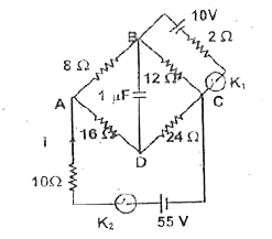
Consider the circuit shown in the figure.
(a) Find the current i flowing through the circuit when the keyK1is open and K2 is closed.
(b) Find the net charge on the capacitor when K1 is open & K2 is.closed and also when K1&K2 both are closed.
(c) What is the change in the current'i, when K1 is closed
 View Solution
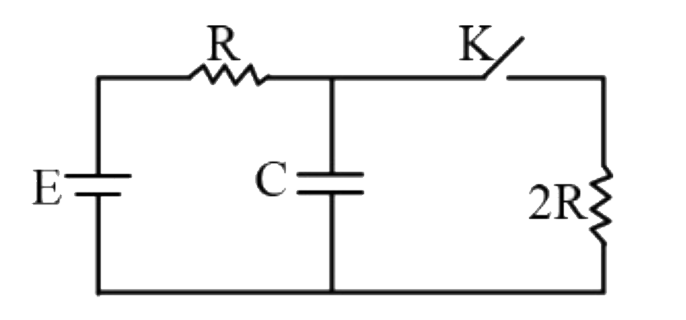
In the given circuit switch K is open. The charge on the capacitor is C is steady-state is q1 Now the key is closed and steady-state charge on C is q2 The ratio of charges q1/q2 is -
 View Solution
Two capacitors C1=C and C2=3C are connected as shown in figure, Initially, key K is open and capacitor C1 holds charge Q. After closing the key K, the charge on each capacitor at steady state will be
View SolutionIn the circuit shown in figure, R(1)=1Ω,R2=2Ω,C1=1μF,C2=2μF and E=6V. Calculate charge on each capacitor in steady state
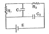 View Solution
In the circuit shown, all capacitors are identical. Initially, the switch is open and the capacitor marked C1 is the only one charged to a value Q0. After the switch is closed and the equilibrium is reestablished, the charge on the capacitor marked C1 is Q. Find the ratio initial change to final charge in capacitor C1.
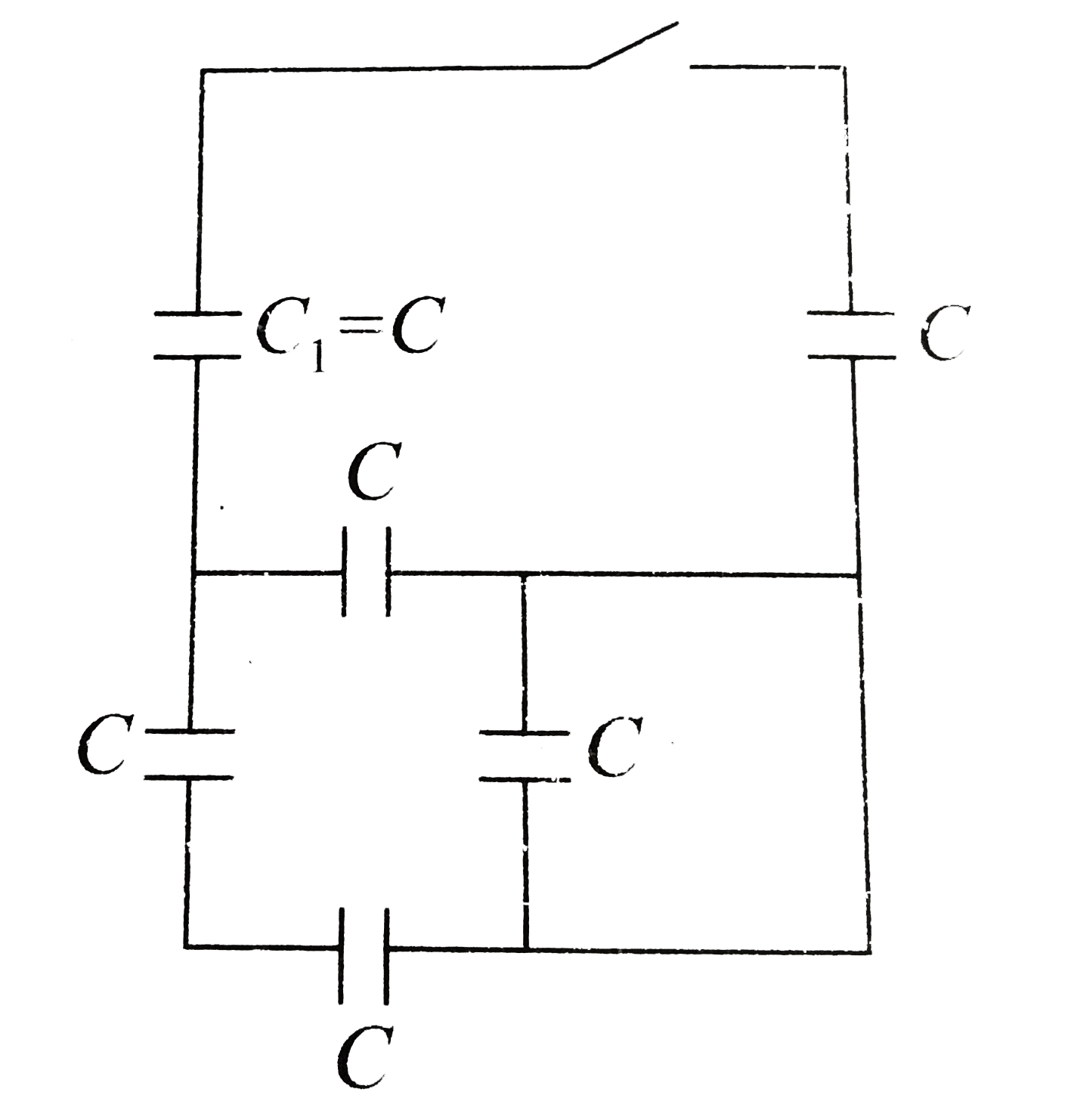 View Solution
In the arrangement shown in figure dielectric constant K1=2 and K2=3. If the capacitance across P and Q are C1 and C2 respectively, then C1/C2 wil be (the gaps shown are negligible)
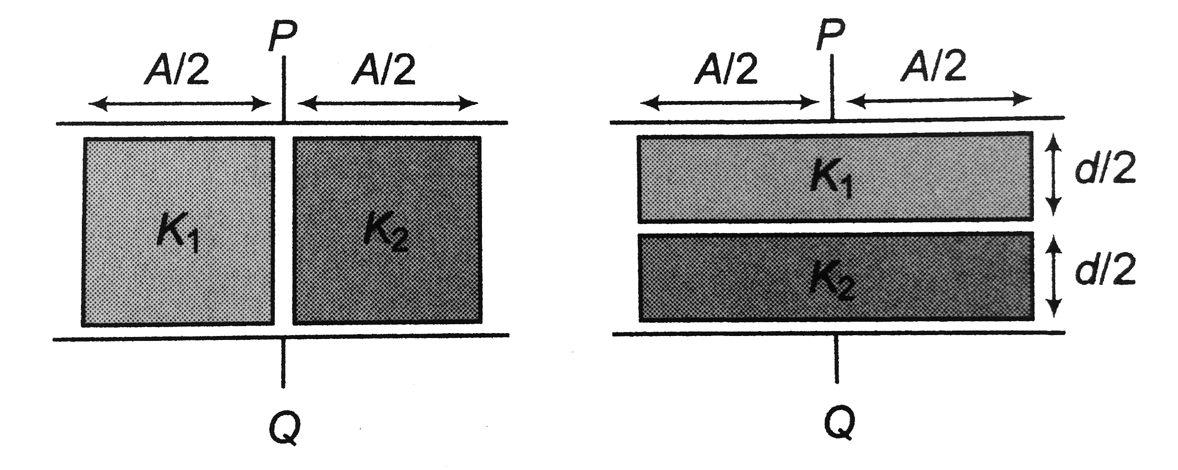 View Solution

