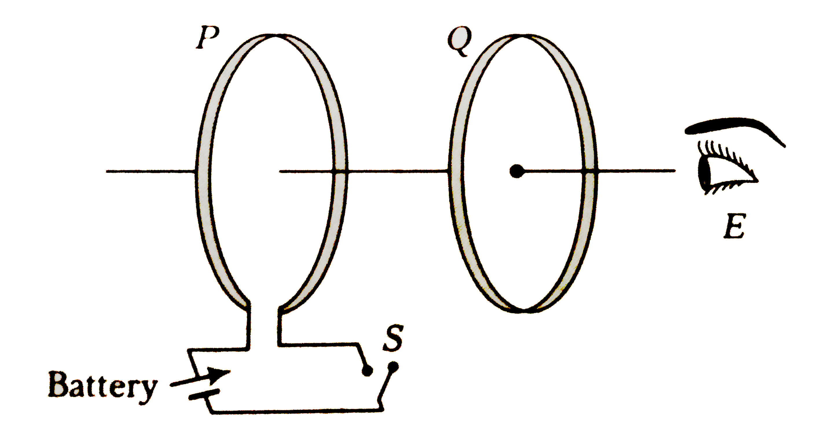
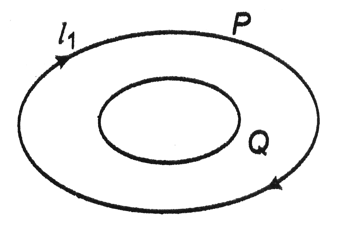
As shown in figure, P and Q are two co-axial conducting loops separated by some distance. When the switch S is closed, a clockwise current IP flows in P (as seen by E) and an induced current IQ1 flows in Q. The switch remains closed for a long time. When S is opened, a current IQ2 flows in Q.
Then, the directions of IQ1 and IQ2 (as seen by E) are
respectively clockwise and Anti-clockwise
both clockwise
both Anti-clockwise
respectively anti-clockwise and clockwise
The correct Answer is:D
Step by step video & image solution for As shown in figure, P and Q are two co-axial conducting loops separated by some distance. When the switch S is closed, a clockwise current I_(P) flows in P (as seen by E) and an induced current I_(Q_(1)) flows in Q. The switch remains closed for a long time. When S is opened, a current I_(Q_(2)) flows in Q. Then, the directions of I_(Q_(1)) and I_(Q_(2)) (as seen by E) are by Physics experts to help you in doubts & scoring excellent marks in Class 12 exams.
Updated on:21/07/2023Topper's Solved these Questions
- ELECTROMAGNETIC INDUCTIONBOOK - AAKASH SERIESCHAPTER - ELECTROMAGNETIC INDUCTIONEXERCISE - EXERCISE-IB
18 Videos
- ELECTROMAGNETIC INDUCTIONBOOK - AAKASH SERIESCHAPTER - ELECTROMAGNETIC INDUCTIONEXERCISE - EXERCISE-II
32 Videos
- ELECTROMAGNETIC INDUCTIONBOOK - AAKASH SERIESCHAPTER - ELECTROMAGNETIC INDUCTIONEXERCISE - Additional Exercise
11 Videos
- ELECTRIC FIELD AND POTENTIALBOOK - AAKASH SERIESCHAPTER - ELECTRIC FIELD AND POTENTIALEXERCISE - PROBLEMS (LEVEL-II)
26 Videos
- ELECTROMAGNETIC WAVESBOOK - AAKASH SERIESCHAPTER - ELECTROMAGNETIC WAVESEXERCISE - EXERCISE -II
22 Videos
Similar Questions
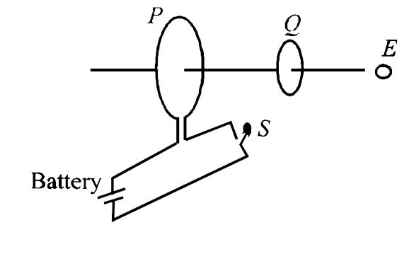
As shown in the figure, P and Q are two coaxial conducting loops separated by some distance. When the switch S is closed, a clockwise current IP (as seen by E) and an induced current IQ1 flows in Q. The switch remains closed for a long time. when S is opened, a current IQ2 flows in Q. Then the direction IQ1andIQ2 (as seen by E) are
View SolutionAs shown in figure, P and Q are two co-axial conducting loops separated by some distance. When the switch S is closed, a clockwise current IP flows in P (as seen by E) and an induced current IQ1 flows in Q. The switch remains closed for a long time. When S is opened, a current IQ2 flows in Q.
Then, the directions of IQ1 and IQ2 (as seen by E) are

View SolutionIf the switch is closed then current will flow.
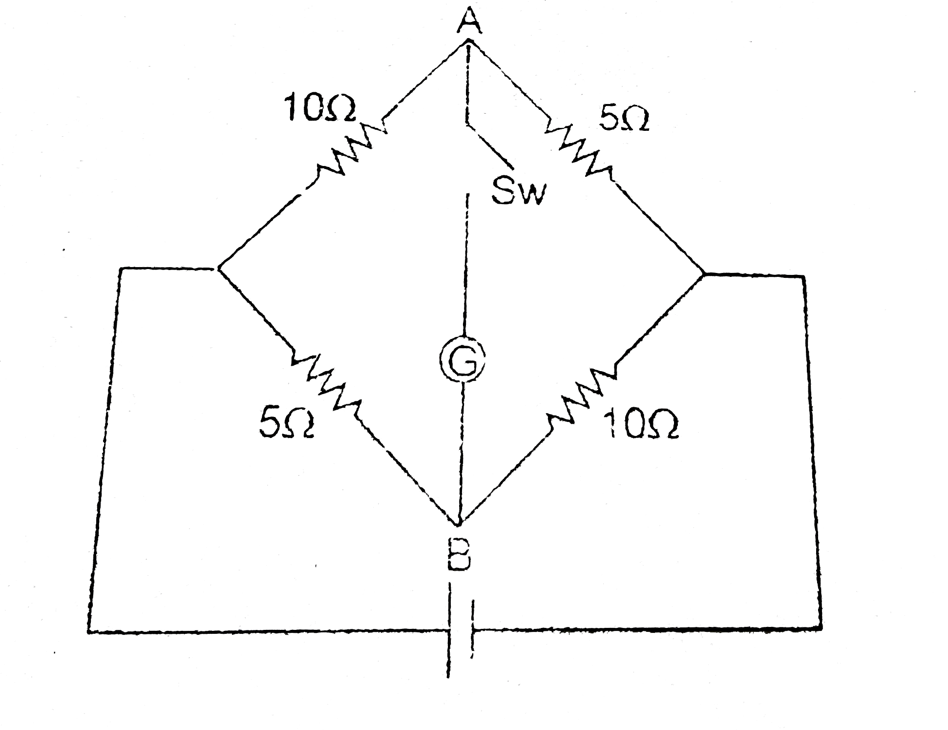
View SolutionIn fig. A2.27, the charge that flows from P to Q when the switch S is closed is
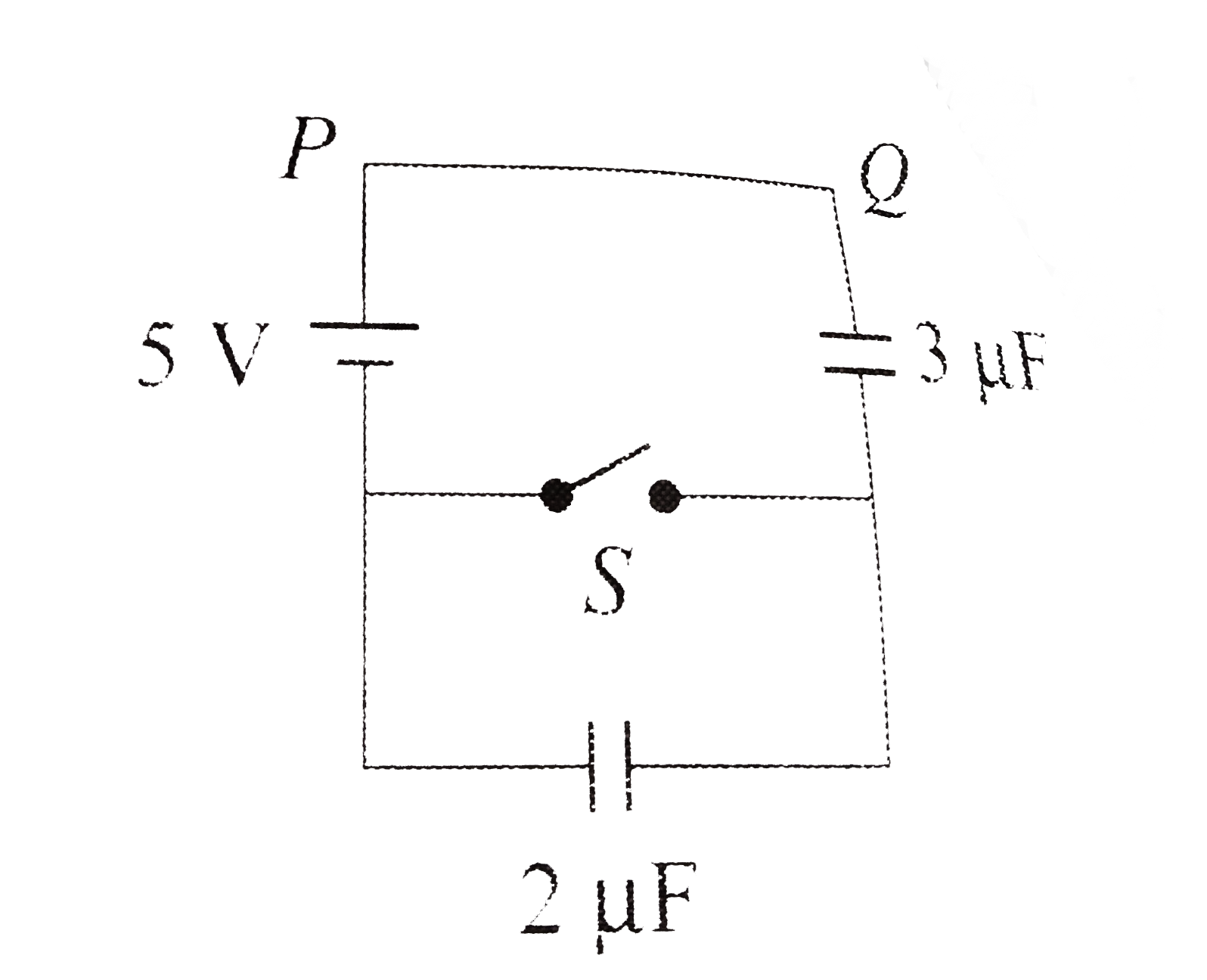
View SolutionWhen the switch S, in the circuit shown, is closed, then the value of current I will be :
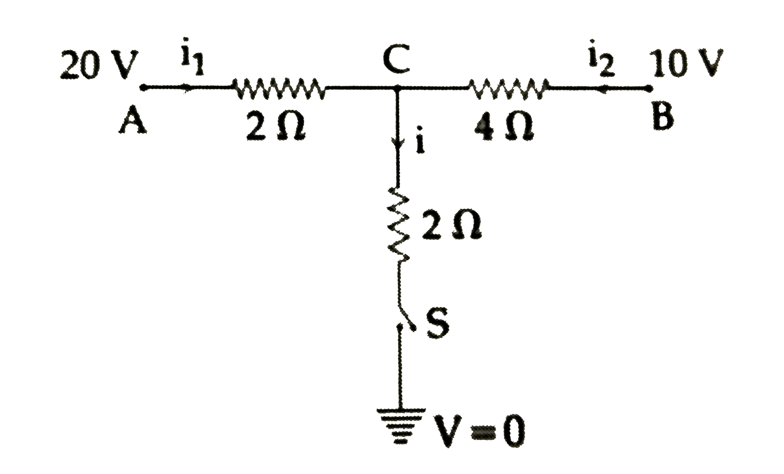
View SolutionIn the circuit shown in the figure The steady state currents i1andi2 in the coils after the switch S is closed are
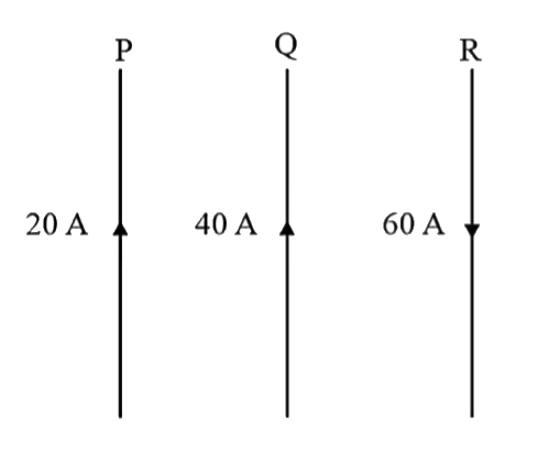
View SolutionP, Q and R are long straight wires in air, carrying currents as shown. The force on Q is directed
View SolutionThe net charge flow between points A and B when the switch is closed in the given circuit and the final potential points Q, P and B are
View SolutionTwo circular loops P and Q are concentric and coplanar as shown in figure. The loop Q is smaller than. P. If the current I1 flowing i loop P is decreasing with time, then the curren I2 in the loop Q
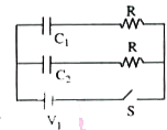
View SolutionIn the circuit shown in figure C1=2C2, Switch S is closed at time t = 0, Let i1andi2 be the currents flowing through C1andC2 at any time t, then the ratio i1/i2
View Solution
