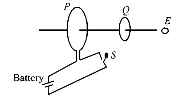
As shown in the figure, P and Q are two coaxial conducting loops separated by some distance. When the switch S is closed, a clockwise current IP (as seen by E) and an induced current IQ1 flows in Q. The switch remains closed for a long time. when S is opened, a current IQ2 flows in Q. Then the direction IQ1andIQ2 (as seen by E) are
respectively clockwise and anti-clockwise
both clockwise
both anti-clockwise
respectively anti-clockwise and clockwise
The correct Answer is:D
When switch S is closed magnetic field lines passing through Q increases in the direction from right to left.
So, according to Lenz's law, induced current in Q, i.e., IQ1 will flow in such a direction, so that the magnetic field lines due to IQ1 passes from left to right through Q. This is possible when IQ1 flows in anti-clockwise direction as seen by E. Opposite is the case when switch S is opened, i.e., IQ2 will be clockwise as seen by E.
Topper's Solved these Questions
- ELECTROMAGNETIC INDUCTIONBOOK - DC PANDEY ENGLISHCHAPTER - ELECTROMAGNETIC INDUCTIONEXERCISE - Medical entrance special format questions
17 Videos
- ELECTROMAGNETIC INDUCTIONBOOK - DC PANDEY ENGLISHCHAPTER - ELECTROMAGNETIC INDUCTIONEXERCISE - Match the columns
5 Videos
- ELECTROMAGNETIC INDUCTIONBOOK - DC PANDEY ENGLISHCHAPTER - ELECTROMAGNETIC INDUCTIONEXERCISE - Check point
60 Videos
- CURRENT ELECTRICITYBOOK - DC PANDEY ENGLISHCHAPTER - CURRENT ELECTRICITYEXERCISE - Medical entrances gallery
97 Videos
- ELECTROMAGNETIC WAVESBOOK - DC PANDEY ENGLISHCHAPTER - ELECTROMAGNETIC WAVESEXERCISE - Sec C
22 Videos
Similar Questions
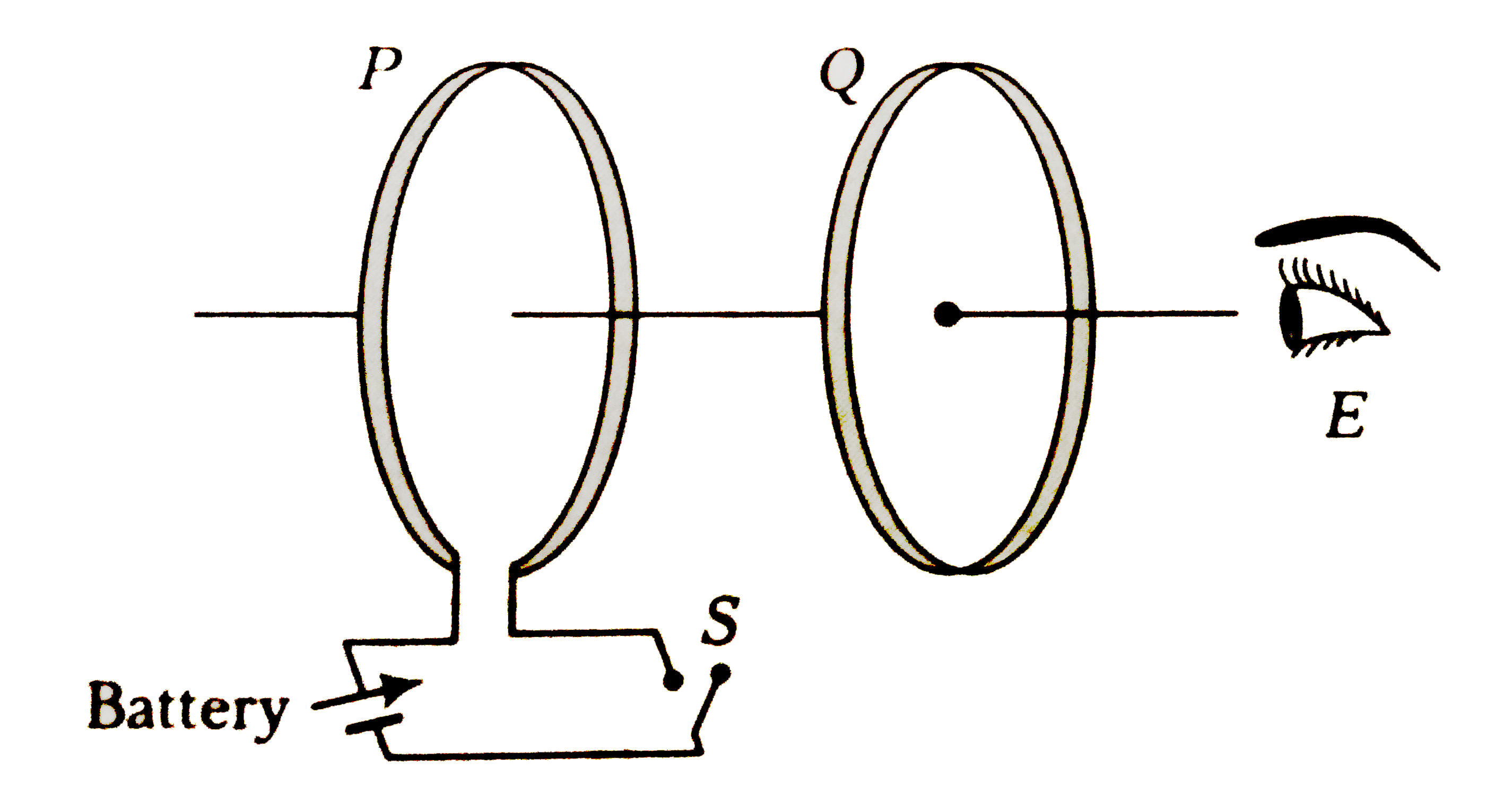
As shown in figure, P and Q are two co-axial conducting loops separated by some distance. When the switch S is closed, a clockwise current IP flows in P (as seen by E) and an induced current IQ1 flows in Q. The switch remains closed for a long time. When S is opened, a current IQ2 flows in Q.
Then, the directions of IQ1 and IQ2 (as seen by E) are
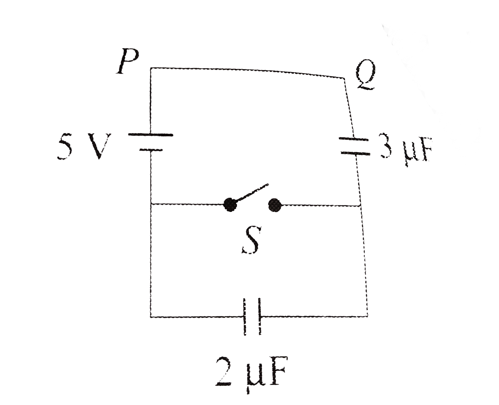
View SolutionIn fig. A2.27, the charge that flows from P to Q when the switch S is closed is
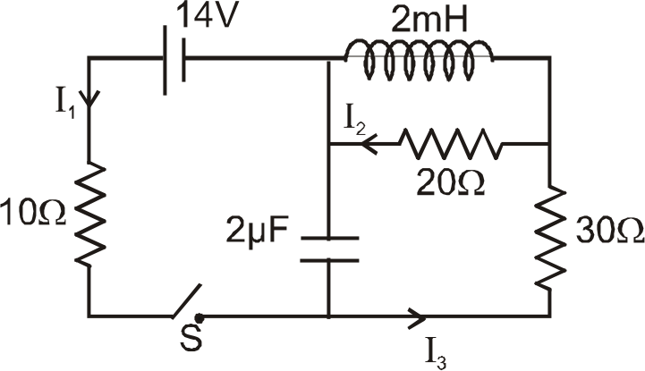
View SolutionIn the circuit shown, the switch is closed at t=0, the currents I1,I2 and I3 are
View SolutionWhen the switch S, in the circuit shown, is closed, then the value of current I will be :
View SolutionIn the circuit shown in the figure The steady state currents i1andi2 in the coils after the switch S is closed are
View SolutionIn the circuit shown in figure switch S is closed at time t=0
Current I from the battery at time t is given by
View SolutionIn the circuit shown switch S is closed at t=0. Let i1 and i2 be the current at any finite time t then the ratio i1i2
View SolutionIn the circuit shwon in fig. switch S is closed at time t = 0. Let I1andI2 be the currents at any finite time t, then the ratio I1/I2
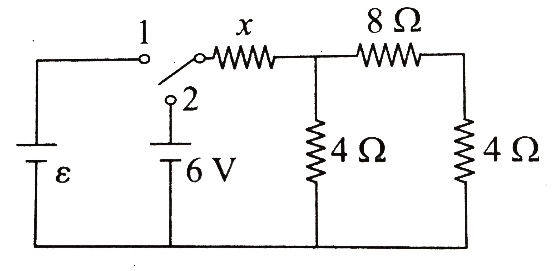
View SolutionWhen the switch 1 is closed, the current through the 8Ω resistance is 0.75A. When the switch 2 is closed (only), the current through the resistance marked x is 1 A. The value of E is
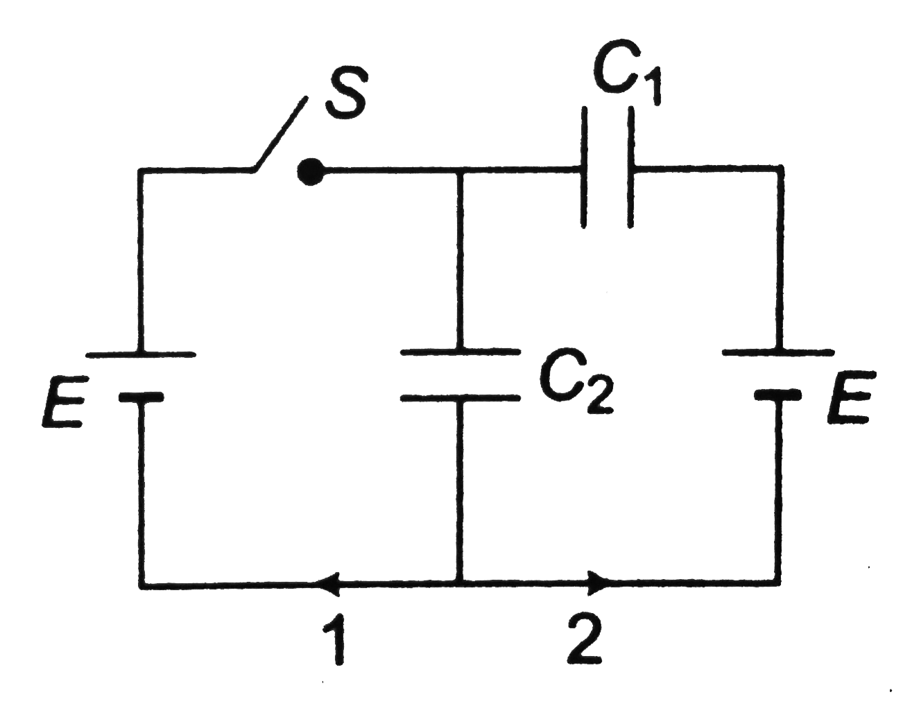
View SolutionIn the given circuit diagram, find the charges which flow through directions 1 and 2 when switch S is closed.
View Solution
