An electric potential difference will be induced between the ends of the conductor shown in the figure, if the conductor moves in the direction shown by
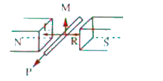
P
R
L
M
The correct Answer is:D
Step by step video & image solution for An electric potential difference will be induced between the ends of the conductor shown in the figure, if the conductor moves in the direction shown by by Physics experts to help you in doubts & scoring excellent marks in Class 12 exams.
Updated on:21/07/2023Topper's Solved these Questions
- ELECTROMAGNETIC INDUCTIONBOOK - AAKASH SERIESCHAPTER - ELECTROMAGNETIC INDUCTIONEXERCISE - EXERCISE-IB
18 Videos
- ELECTROMAGNETIC INDUCTIONBOOK - AAKASH SERIESCHAPTER - ELECTROMAGNETIC INDUCTIONEXERCISE - EXERCISE-II
32 Videos
- ELECTROMAGNETIC INDUCTIONBOOK - AAKASH SERIESCHAPTER - ELECTROMAGNETIC INDUCTIONEXERCISE - Additional Exercise
11 Videos
- ELECTRIC FIELD AND POTENTIALBOOK - AAKASH SERIESCHAPTER - ELECTRIC FIELD AND POTENTIALEXERCISE - PROBLEMS (LEVEL-II)
26 Videos
- ELECTROMAGNETIC WAVESBOOK - AAKASH SERIESCHAPTER - ELECTROMAGNETIC WAVESEXERCISE - EXERCISE -II
22 Videos
Similar Questions
Knowledge Check
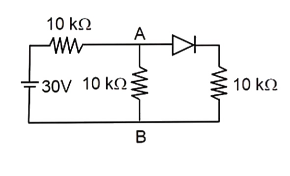
What is the potential difference between the points A and B in the circuit diagram shown in figure ?
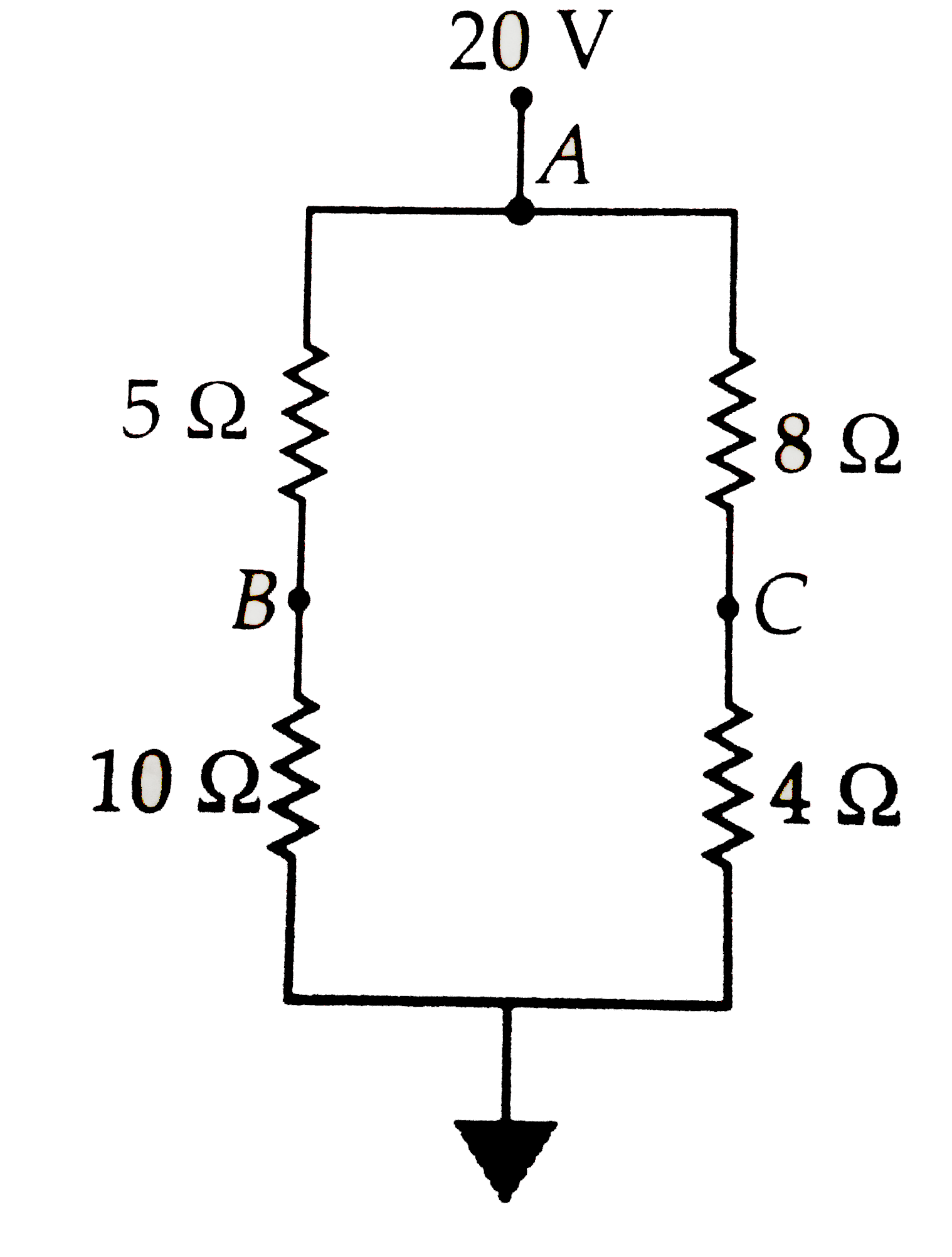 A203VB103VC20√3VD10√3V
The potential difference between the points A and B in the following circuit shown in the figure:-
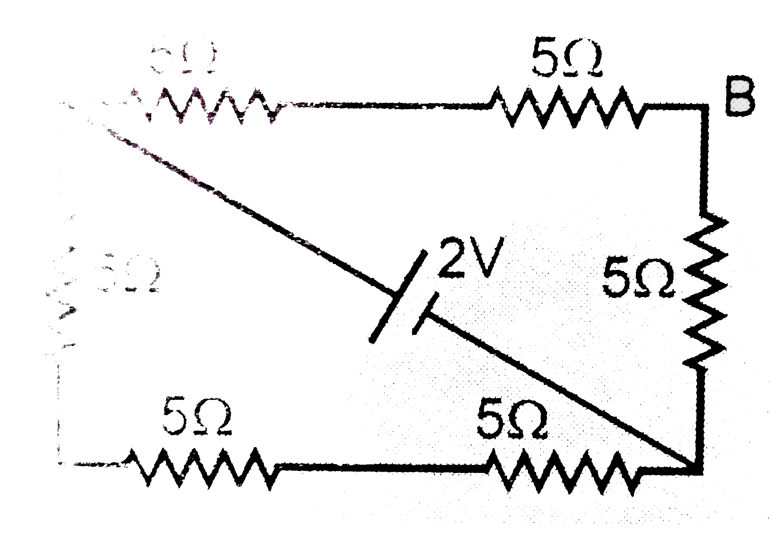
View SolutionConsider a conductor of length 40 cm where a potential difference of 10V is maintained between the ends of the conductor. Find the mobility of the electrons provided the drift velocity of the electrons is 5×10⁻⁶ms−1
View SolutionFor a given metallic conductor , the variation of current through the conductor with potential difference applied across the conductor is shown in the given graph. If temperature of the conductor is increased , then slope tan theta
_PHY_E01_0010_Q01.png)
View SolutionIn the network shown in the figure, the potential difference between A and B is :
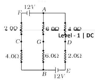
View SolutionFind the potential difference between A and B as shown in the figure
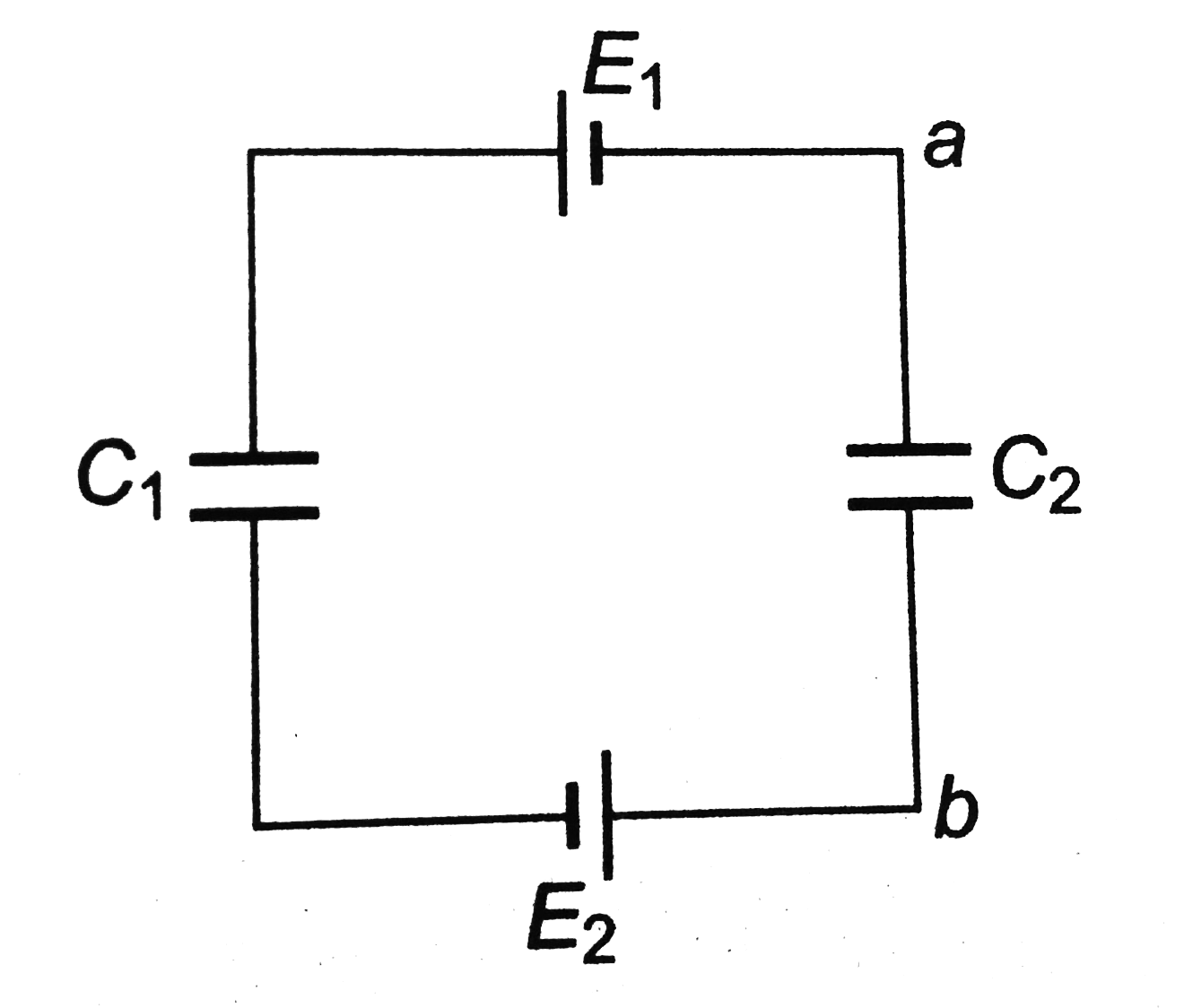
View SolutionThe potential difference between points a and b of circuits shown in figure is
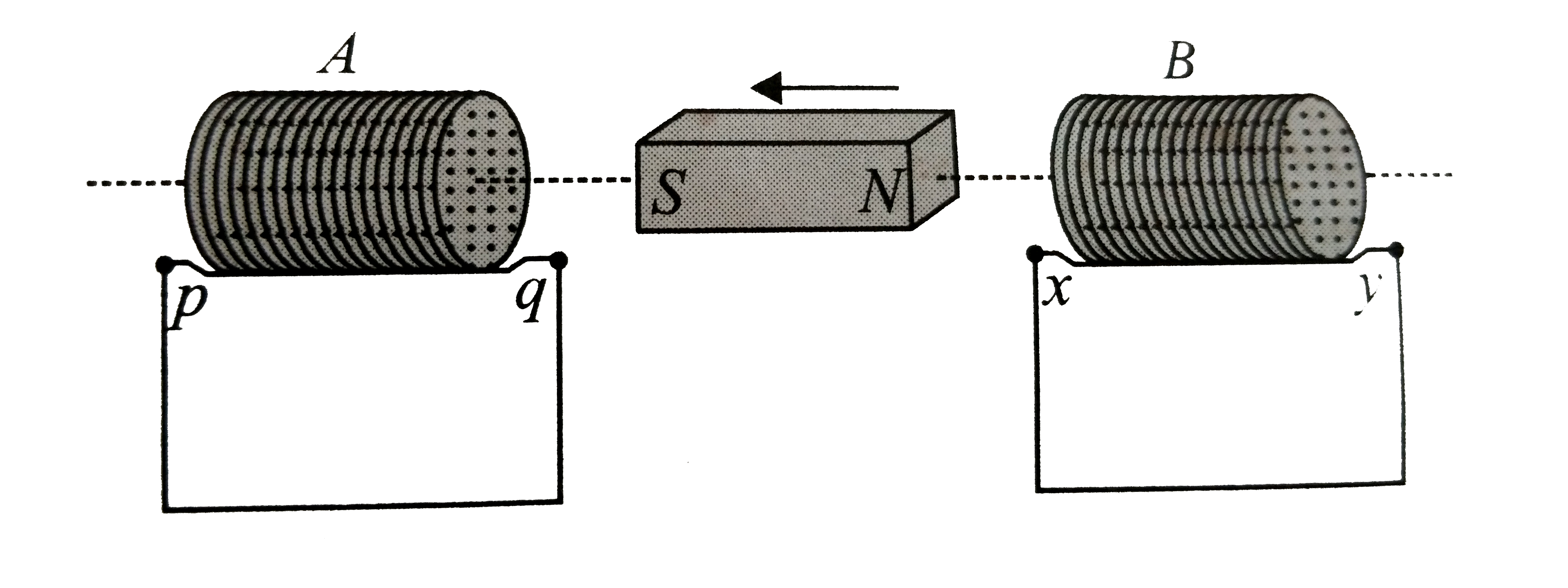
View SolutionThe direction of induced currnet in the coils A and B in the situation shown in the figure is
View Solution


