While doing their experiment on finding the equivalent resistance of two resistors connected in series. The student A,B and C set up their circuits as shown. The correct set up is that of:
 Solution in Punjabi
Students A and B
Students B and C
Students C and A
All the three students.
Step by step video & image solution for While doing their experiment on finding the equivalent resistance of two resistors connected in series. The student A,B and C set up their circuits as shown. The correct set up is that of: by Physics experts to help you in doubts & scoring excellent marks in Class 10 exams.
Topper's Solved these Questions
Similar Questions
Define electric current and give its unit
02:17View SolutionWrite the S.I. unit of magnetic field →B.
01:49View SolutionTo determine the equivalent resistance of two resistors when connected in series, a student arrnaged the circuit components as shown in (Fig. 3.63) But he did not succeed to achieve the objective. Which mistake has been committed by him in setting up the circuit ?
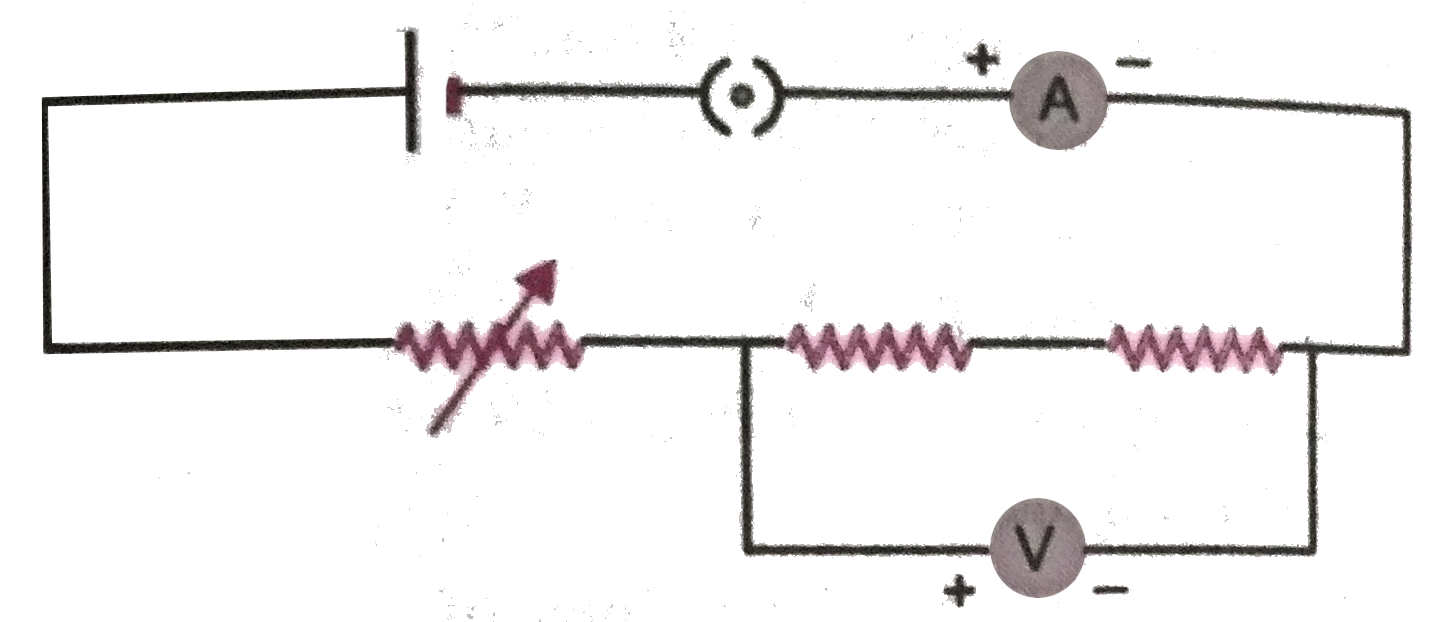 .02:54View Solution
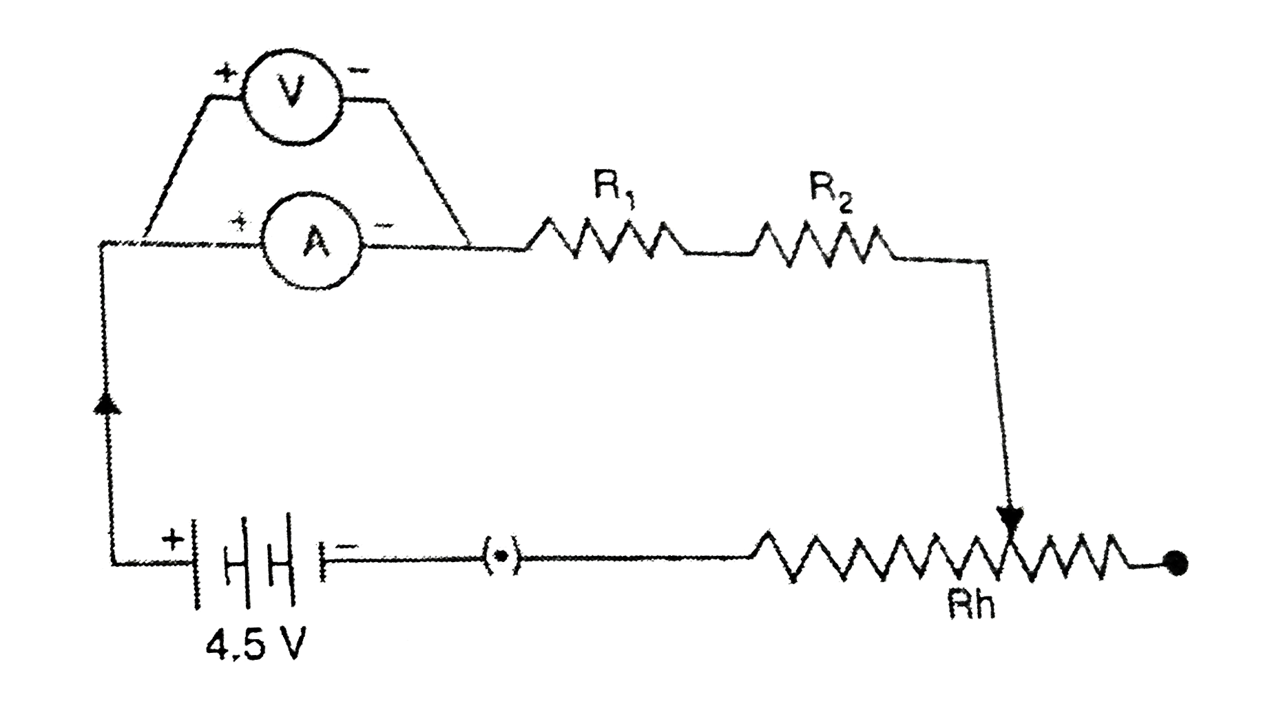
In an experiment to find the equivalent resistance of two resistors connected in series, a student uses the circuit shown :
This circuit will give :
 02:32View Solution
A student stes up an electric circuit shown here for finding the equivalent resistance of two resistors in series : In this circuit, the :
01:47View SolutionChoose the appropriate set of apparatus for performing the experiment to determine the equivalent resistance of two resistors when connected in series :
02:07View SolutionIn the experiment on finding the equivalent resistance of two resistors connected in series, three students connected the ammeter in their circuits in the three ways X, Y and Z shown here.

Assuming their ammeters to be ideal, the ammeters have been correctly connected in01:49View SolutionIn the experiment on finding the equivalent resistance of two resistors, connected in parallel, three students connected the voltmeter in their circuits, in the three ways X, Y and Z shown here. The voltmeter has been correctly connected in
02:04View SolutionFour student have made the following circuit diagrams for determining the equivalent resistance of two resistors connected in series :
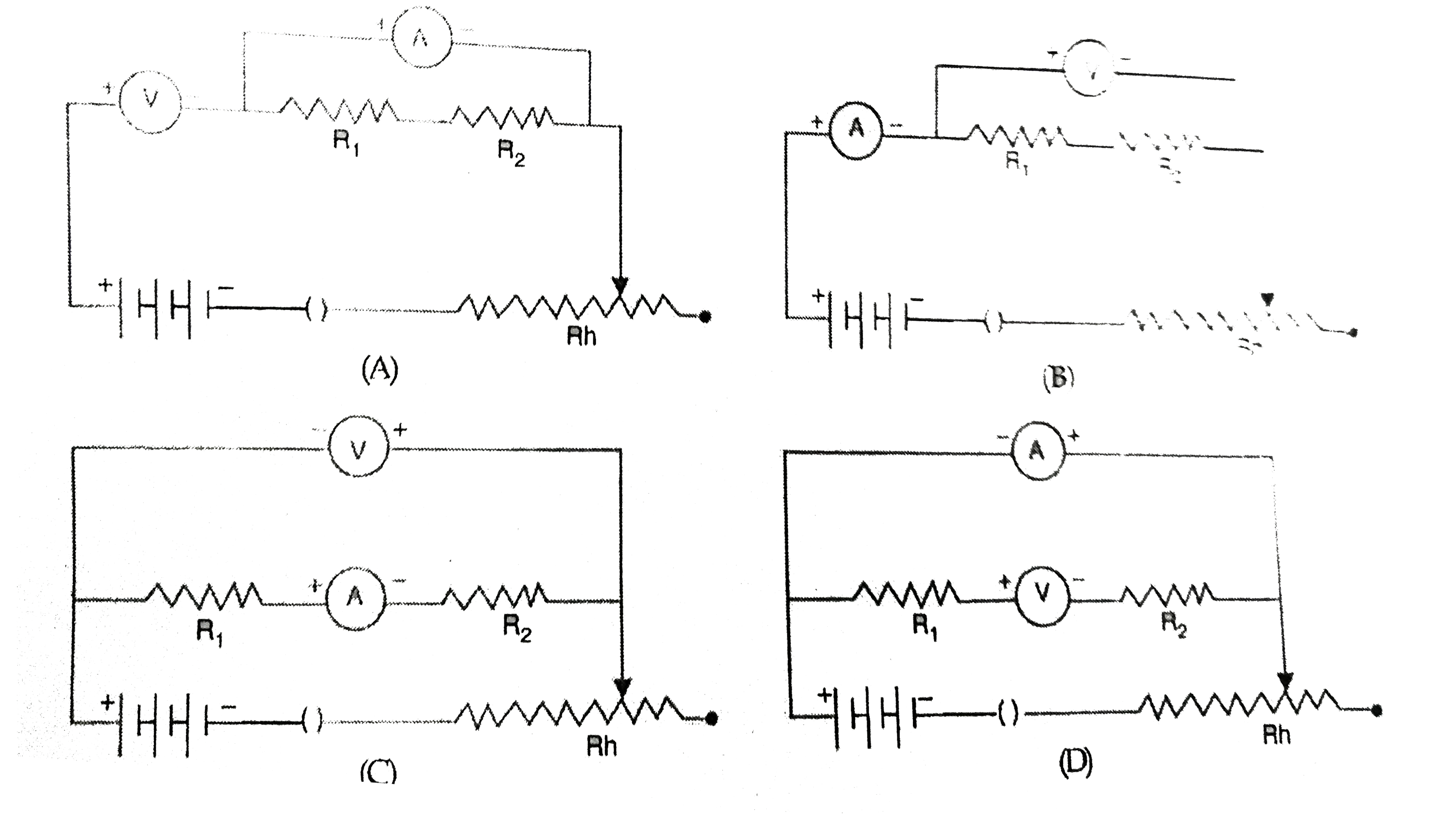
The correct circuit diagram is :02:05View SolutionConsider the following four circuits P, Q, R and S which have been set up to find the resultant resistance of two resistors combined in parallel : The correct way of connecting the ammeter and voltmeter in the circuit is :
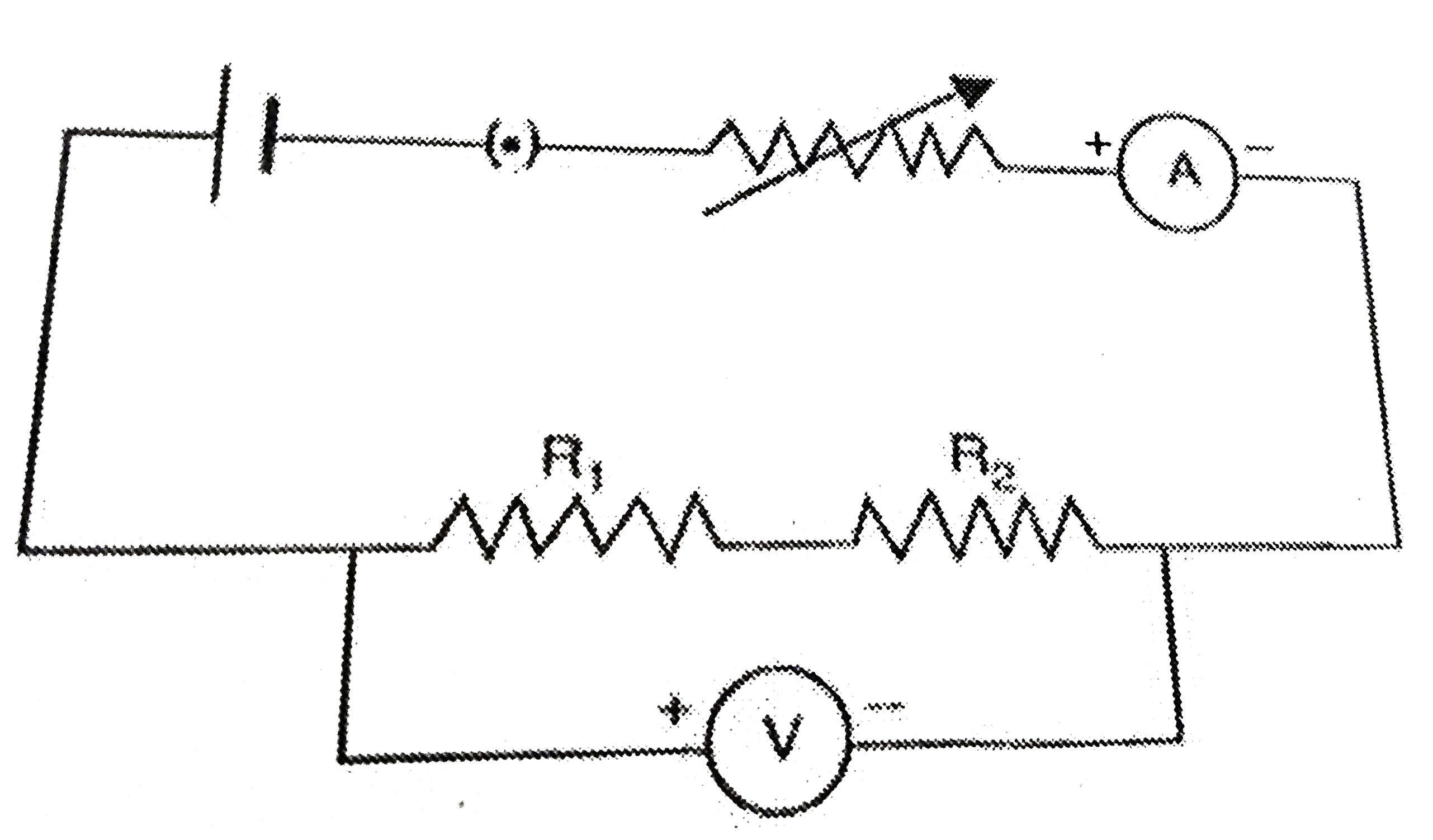
01:51View SolutionTo find the resultant resistance of two resistors when connected in series, a student arranged the various components according to the circuit shown alongside :
The student, however, did not succeed in his objective. Which of the following mistake has been made by the student in setting up the circuit ?
 02:58View Solution
श्रेणीक्रम में संयोजित दो प्रतिरोधों का तुल्य प्रतिरोध कितना होगा?
View SolutionFind the equivalent resistance of the two resistors connected in parallel series.
View SolutionTo determine the equivalent resistance of two resistors when connected in series, a student arranged the circuit components as shown in the diagram. But he did not succeed to achieve the objective.
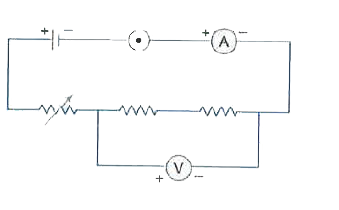
Which mistake has been committed by him in setting up the circuit?View SolutionIn an experiment to find the equivalent resistance of a series combination of two resistors R1 and R2,a student uses the circuit shown here. Will the circuit give the correct reading for current I and voltage V ? Justify your answer.
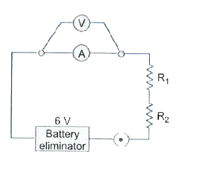 02:07View Solution
Two resistors are connected (a) in series (b) in parallel. The equivalent resistance in the two cases are 9 ohm and respectors. Then the resistances of the component resistors are
03:06View Solution

