For the circuit shown in the figure
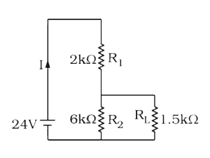
the current I through the battery is 7.5 mA
the potential difference across RL is 18 V
ratio of powers dissipated in R1andR2 is 3
If R1andR2 are interchanged, the magnitude of the power dissipated in RL will decrease by a factor of 9
R→tal=2+6×1.56+1.5=32kΩ
(a) I=24V32kΩ=7.5mA=IR1⇒IR2=(RLRL+R2)I⇒IR2=1.57.5×7.5=1.5mA
(b) VR1=(JRL(RL)=9V ( c) PR1PR2=(r2R1)R1(r2R2)R2=(7.5)2(2)(1.5)2(6)=253
When R1andR2 are inter changed, then R2RLR2+RL=2×1.53.5=67kΩ
Now potential difference across RL will be VL=24[6/76+6/7]=3V.Earlier it was 9V
SInce P=V2RorP∝V2
In new situation potential difference has been decreased three times. Therefore, power dissipated will decreases be a factor 9.
Topper's Solved these Questions
- DC CIRCUITBOOK - VMC MODULES ENGLISHCHAPTER - DC CIRCUITEXERCISE - LEVEL-1 JEE MAIN ARCHIVE
93 Videos
- CURRENT ELECTRICITYBOOK - VMC MODULES ENGLISHCHAPTER - CURRENT ELECTRICITYEXERCISE - IN-CHAPTER EXERCISE-F
10 Videos
- DYNAMICS OF A PARTICLEBOOK - VMC MODULES ENGLISHCHAPTER - DYNAMICS OF A PARTICLEEXERCISE - JEE Advance (Archive) Level - II (SINGLE OPTION CORRECT TYPE )
31 Videos
Similar Questions
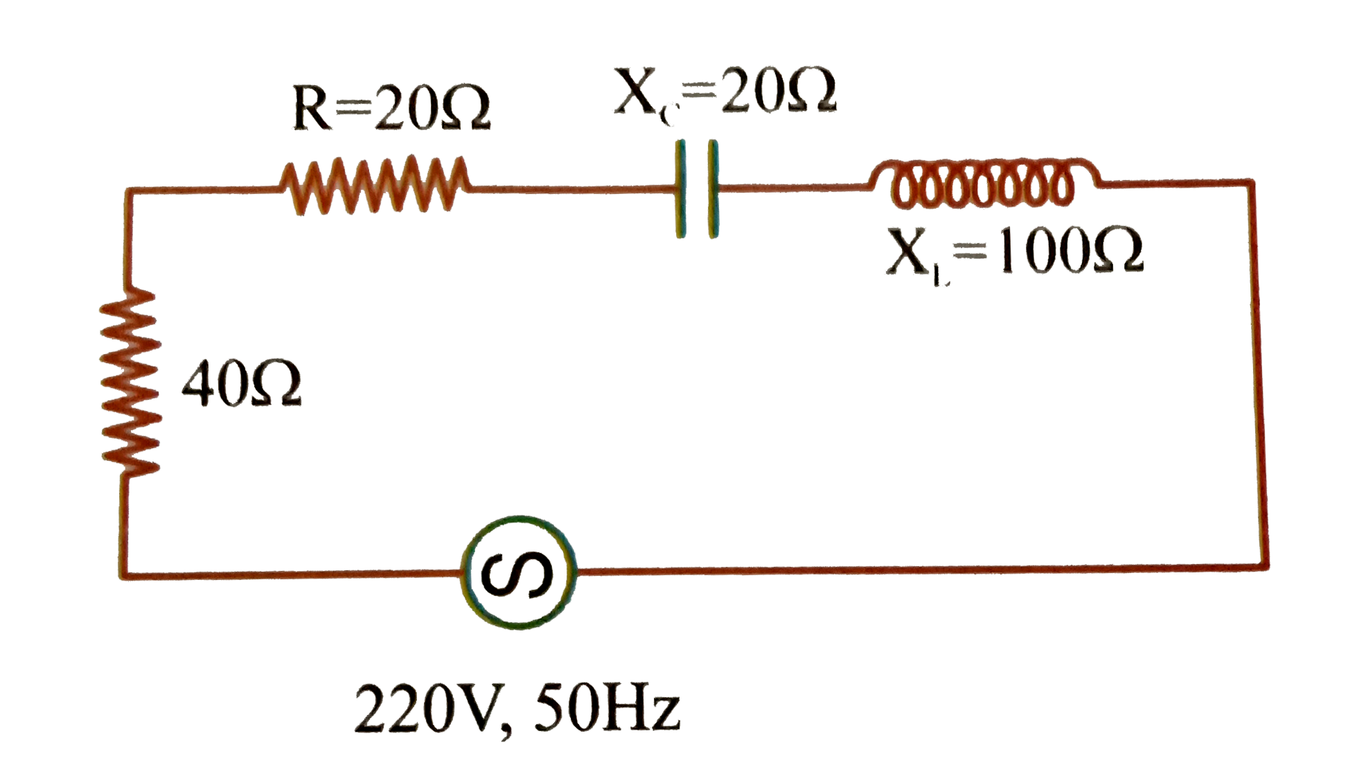
Impendance of the circuit shown in the figure is

View SolutionIn the circuit shown in the figure
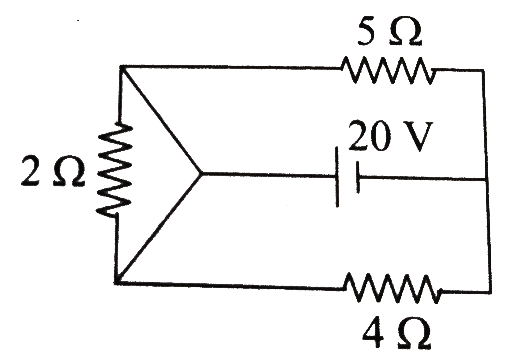 .
.
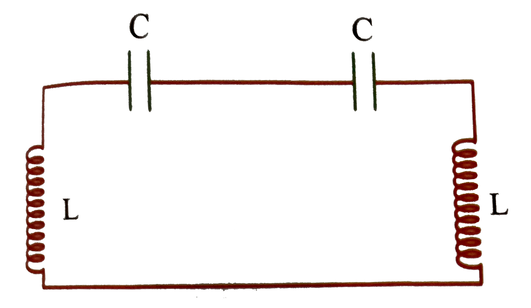
View SolutionThe natural frequency of the circuit shown in the figure is
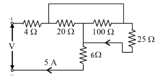
View SolutionIn the circuit shown in the figure , V must be -
View SolutionThe power factor of the circuit shown in the figure is
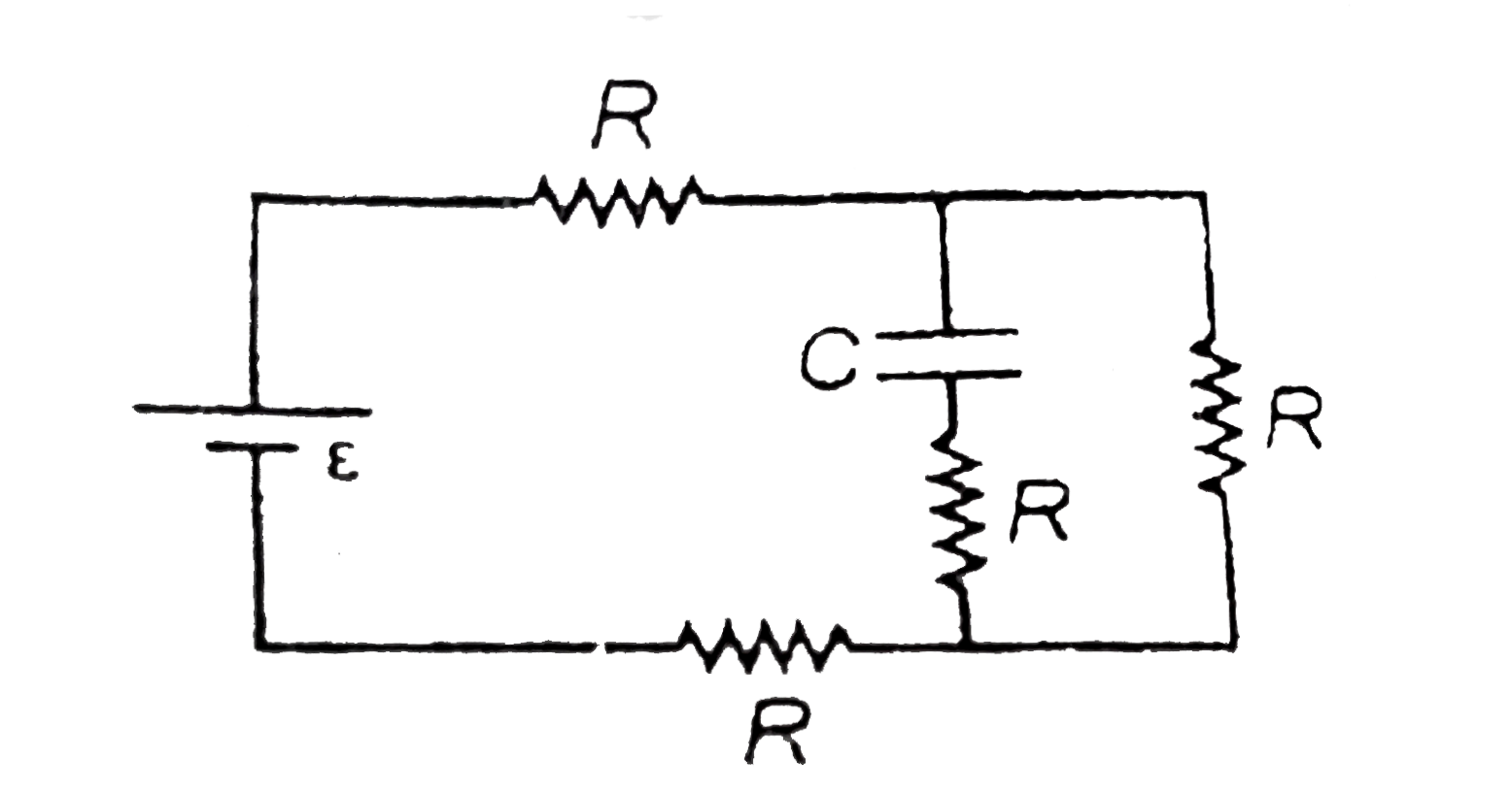
View SolutionThe time constant of the circuit shown in the figure is
View SolutionIn the circuit shown in the figure
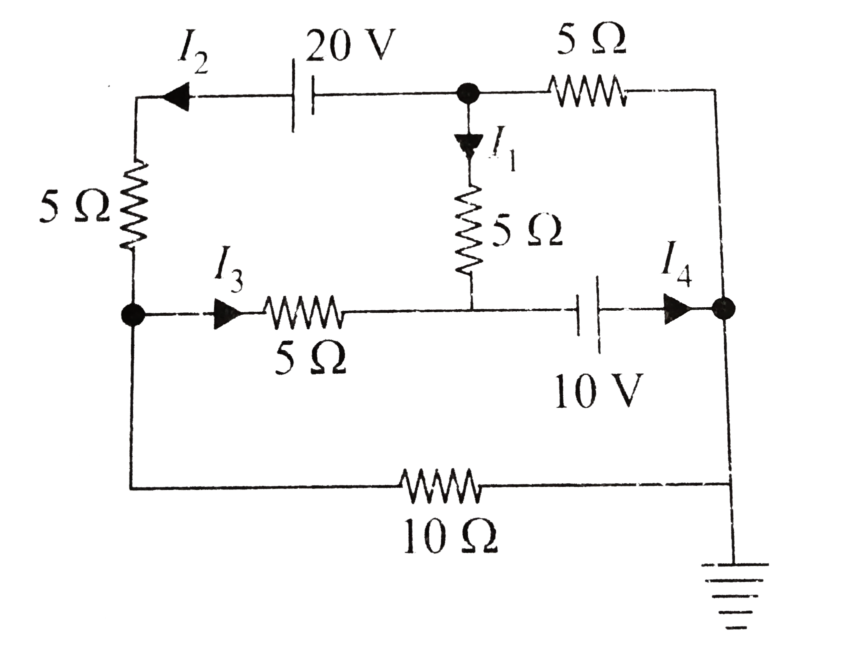 .
.
The value of current I4 is
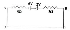
View SolutionThe internal resistanes of cells in the circuit shown in the figure are negligible. The current in the circuit is
View SolutionIn the circuit shown in the figure, in steady state:
The current drawn from the battery is
View SolutionConsider the circuit shown in the figure. Taking the potential to be zero at the negative terminal of the battery :
View Solution
