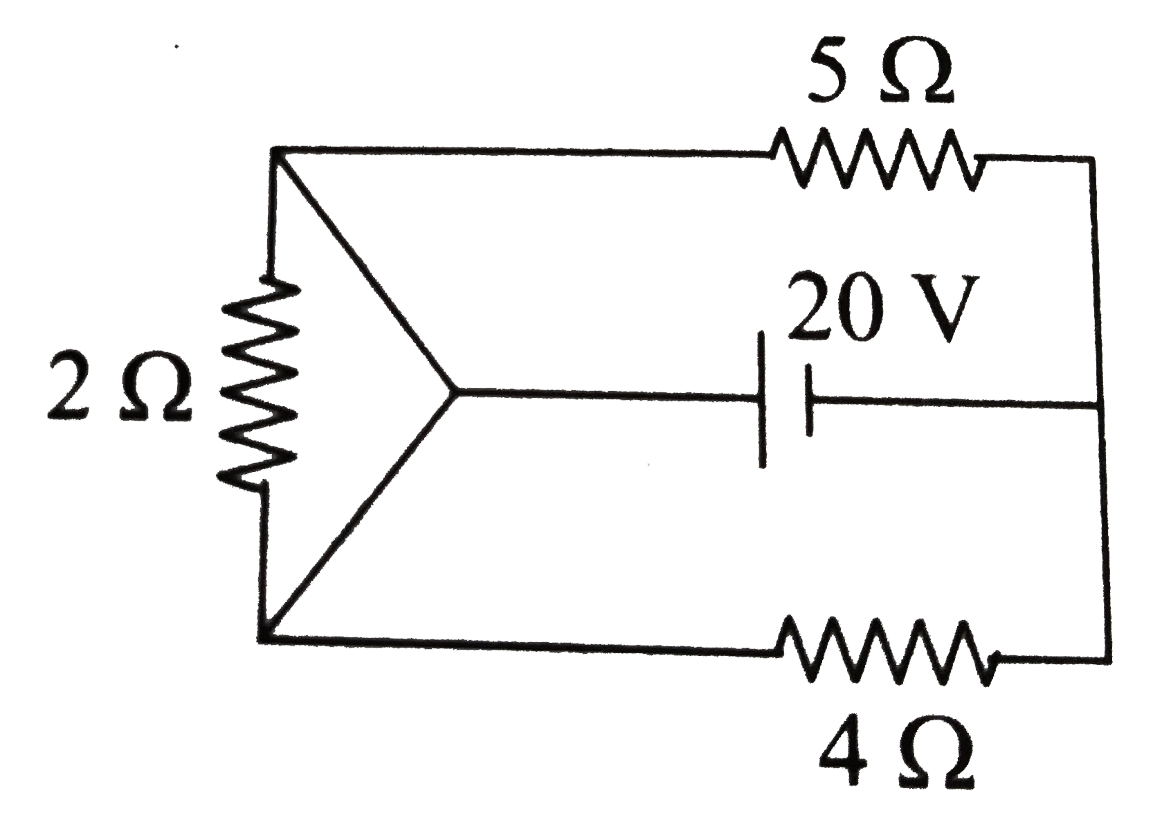
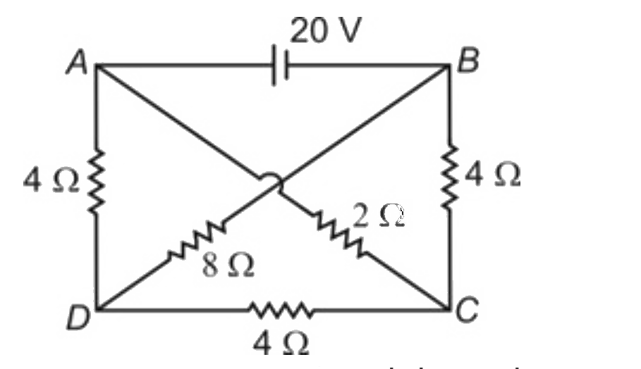
In the circuit shown in the figure
 .
.
current passing through 2Ω resistance is zero.
current passing through 4Ω resistance is 5A
current passing through 5Ω resistance is 4A.
potential difference across 2Ω resistance is zero.
The correct Answer is:A, B, C, D
a., b., c., d.
2Ω resistance will be short-circuited as potential drop across
it is 0 also 4Ω and 5Ω are in parallel.
1R=4+54×5=920
I=2020×9=9A⇒I1×4=(9−I1)×5
I1=5A,I−I1=4A .
Topper's Solved these Questions
- MISCELLANEOUS VOLUME 3BOOK - CENGAGE PHYSICS ENGLISHCHAPTER - MISCELLANEOUS VOLUME 3EXERCISE - Assertion and Reason
8 Videos
- MISCELLANEOUS VOLUME 3BOOK - CENGAGE PHYSICS ENGLISHCHAPTER - MISCELLANEOUS VOLUME 3EXERCISE - Integer Answer Type
11 Videos
- MISCELLANEOUS VOLUME 3BOOK - CENGAGE PHYSICS ENGLISHCHAPTER - MISCELLANEOUS VOLUME 3EXERCISE - Assertion-Reasoning Type
1 Videos
- MAGNETIC FIELD AND MAGNETIC FORCESBOOK - CENGAGE PHYSICS ENGLISHCHAPTER - MAGNETIC FIELD AND MAGNETIC FORCESEXERCISE - Multiple Correct Answer type
2 Videos
- MISCELLANEOUS VOLUME 5BOOK - CENGAGE PHYSICS ENGLISHCHAPTER - MISCELLANEOUS VOLUME 5EXERCISE - Integer
12 Videos
Similar Questions
In the circuit as shown in the figure the effective capacitance between A and B is
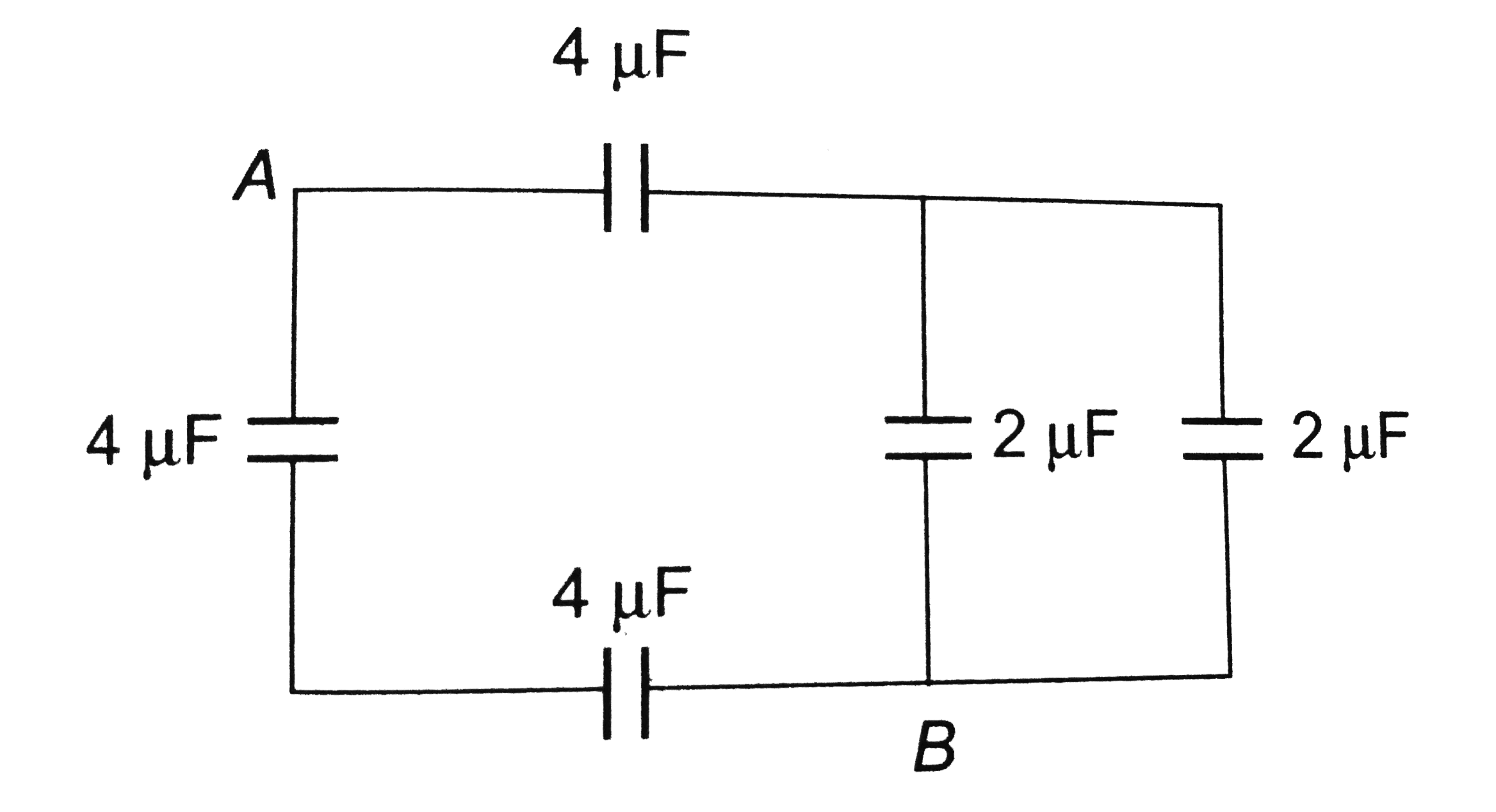
View SolutionIn the circuit as shown in the figure the effective capacitance between A and B is

View SolutionFor the circuit shown in the figure
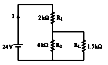
View SolutionFor the circuit shown in the figure
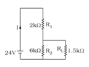
View SolutionFor the circuit shown in the figure :
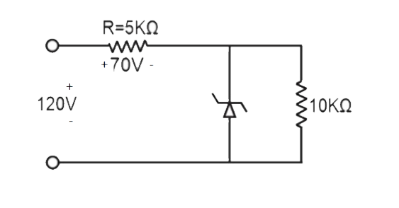
View SolutionConsider the circuit shown in the figure. The current I3 is equal to
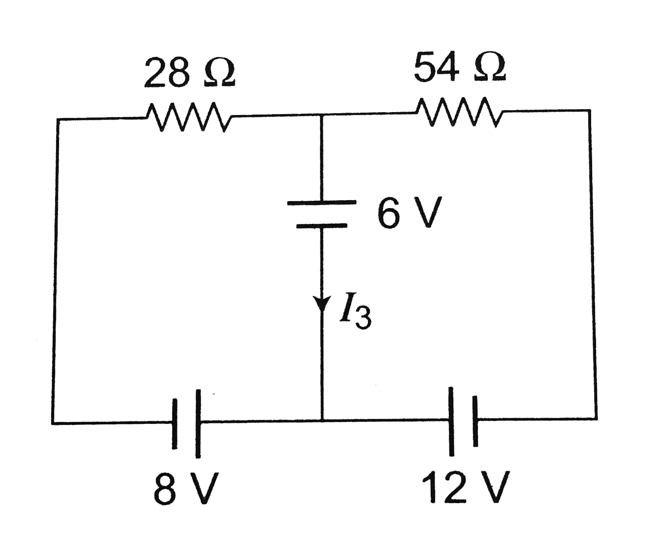
View SolutionConsider the circuit shown in the figure. Taking the potential to be zero at the negative terminal of the battery :
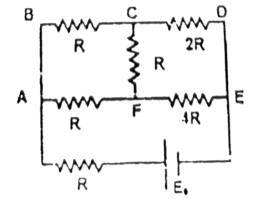
View SolutionConsider the circuit shown in the figure.
Which of the following statements are correct ?
View SolutionThe current in the resistor R3 in the circuit as shown in the figure is

View SolutionImpendance of the circuit shown in the figure is

View Solution
