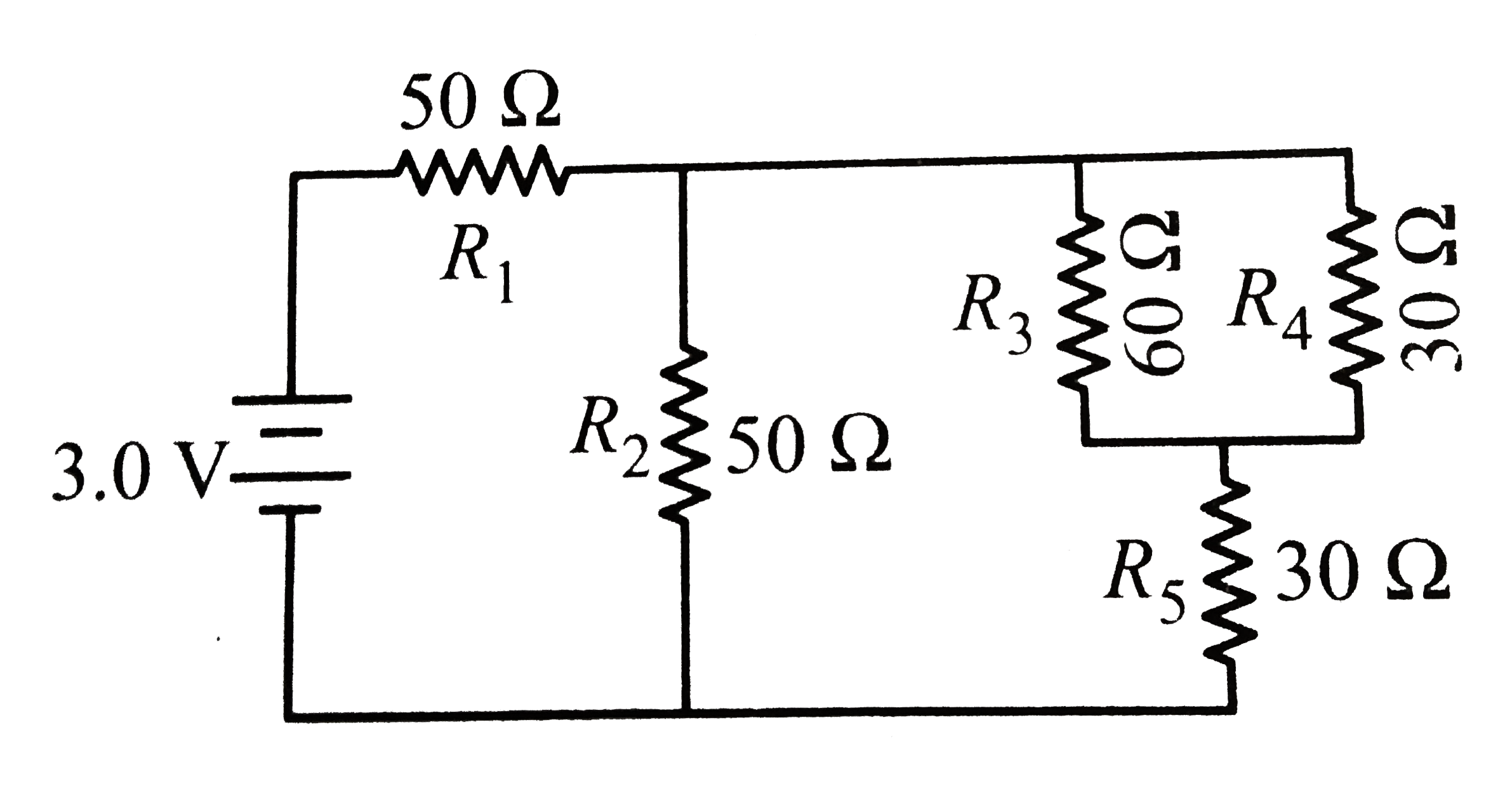
In the circuit shown, the resistances are given in ohms and the battery is assumed ideal with emf equal to 3.0 V.
0.4V
0.6V
1.2V
1.5V
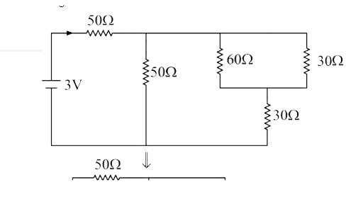
Req=75Ω
i=375A
Use current dividing Rule for current
Topper's Solved these Questions
- DC CIRCUITBOOK - VMC MODULES ENGLISHCHAPTER - DC CIRCUITEXERCISE - LEVEL-1 DAILY TUTORIAL SHEET-3
15 Videos
- DC CIRCUITBOOK - VMC MODULES ENGLISHCHAPTER - DC CIRCUITEXERCISE - LEVEL-1 DAILY TUTORIAL SHEET-4
15 Videos
- DC CIRCUITBOOK - VMC MODULES ENGLISHCHAPTER - DC CIRCUITEXERCISE - LEVEL-1 DAILY TUTORIAL SHEET-1
15 Videos
- CURRENT ELECTRICITYBOOK - VMC MODULES ENGLISHCHAPTER - CURRENT ELECTRICITYEXERCISE - IN-CHAPTER EXERCISE-F
10 Videos
- DYNAMICS OF A PARTICLEBOOK - VMC MODULES ENGLISHCHAPTER - DYNAMICS OF A PARTICLEEXERCISE - JEE Advance (Archive) Level - II (SINGLE OPTION CORRECT TYPE )
31 Videos
Similar Questions
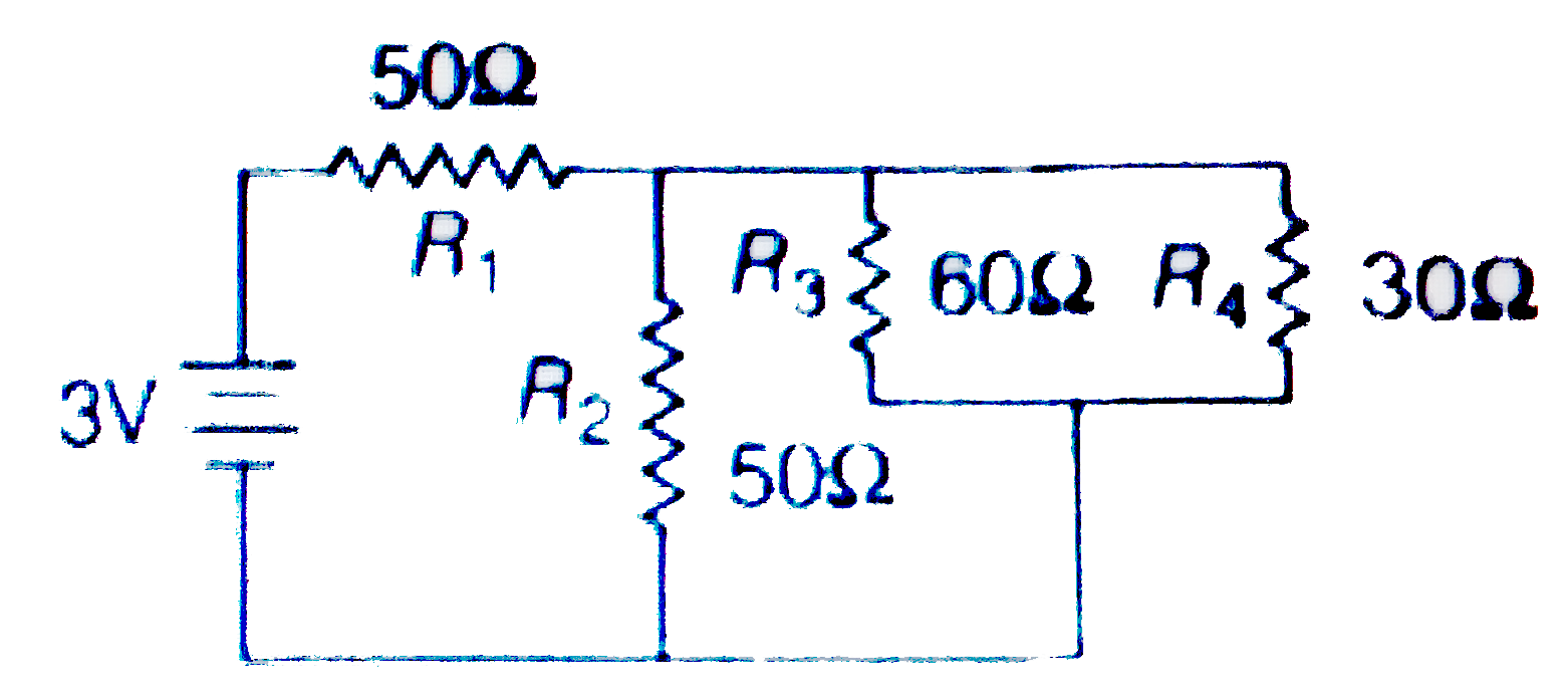
In the circuit shown, the resistance are given ohms and the battery is assumed ideal with end equal to 3.0 volts. The resistance that dissipates the maximum power is
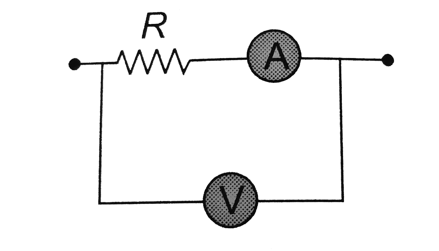
View SolutionIn the circuit shown the resistance of voltmeter is 10000ohm and that of ammeter is 20ohm. The ammeter reading is 0.10amp and voltmeter reading is 12 volts. Then R is equal to
View Solution
Knowledge Check
A battery having 12V emf and internal resistance 3Ω is connected to a resistor. If the current in the circuit is 1A, then the resistance of resistor and lost voltage of the battery when circuit is closed will be
A7Ω,7VB8Ω,8VC9Ω,9VD9Ω,10V
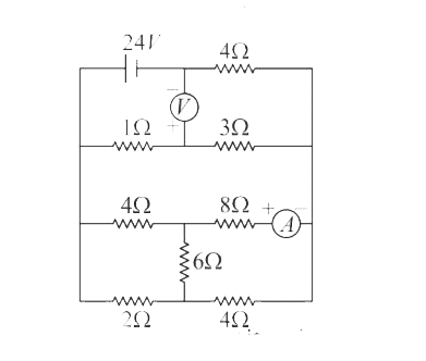
In the circuit shown, the battery, the ammeter and the voltmeter are ideal. Pick the correct choice(s) :
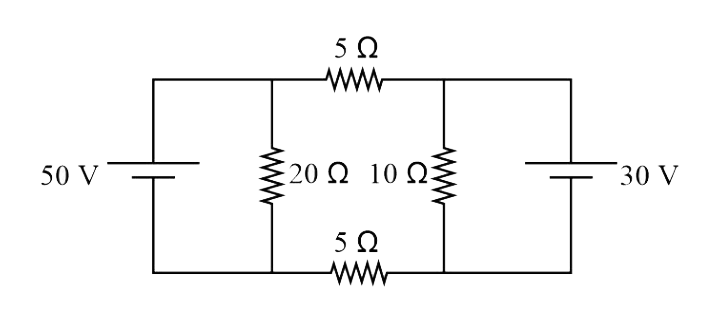
View SolutionIn the circuit shown, current (in A) through the 50 V and 30 V batteries are, resepctively
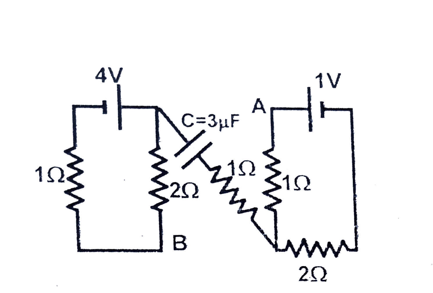
View SolutionIn the circuit shown in the adjacent figure, the batteries are ideal. The charge on the capacitor C is
View SolutionIn the circuit shown,choose the correct option (All batteries are ideal)
_PHY_E05_285_Q01.png)
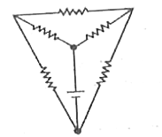
View SolutionIf all resistors in the shown network are of equal resistance, and the battery is of emf equal to 10 V and internal resistance equal to 1Ω, what should be resistance of each resistor so that the battery delivers maximum power
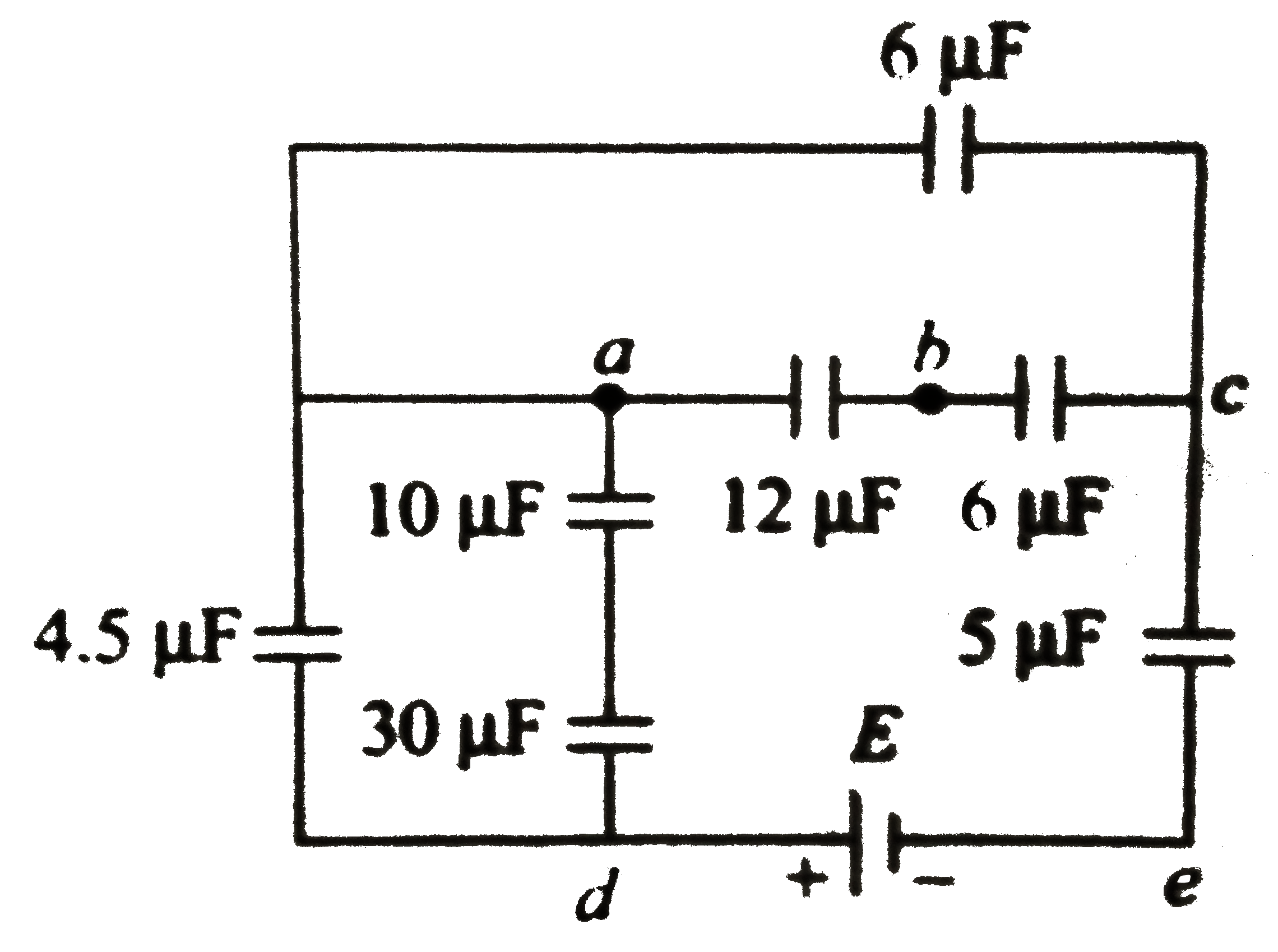
View SolutionIn the circuit shown in the potential difference between the point a and b is 4V, Find the emf ε of the battery. Assume that before connecting the battery in the circuit, all the capacitors were uncharged.
 .
.
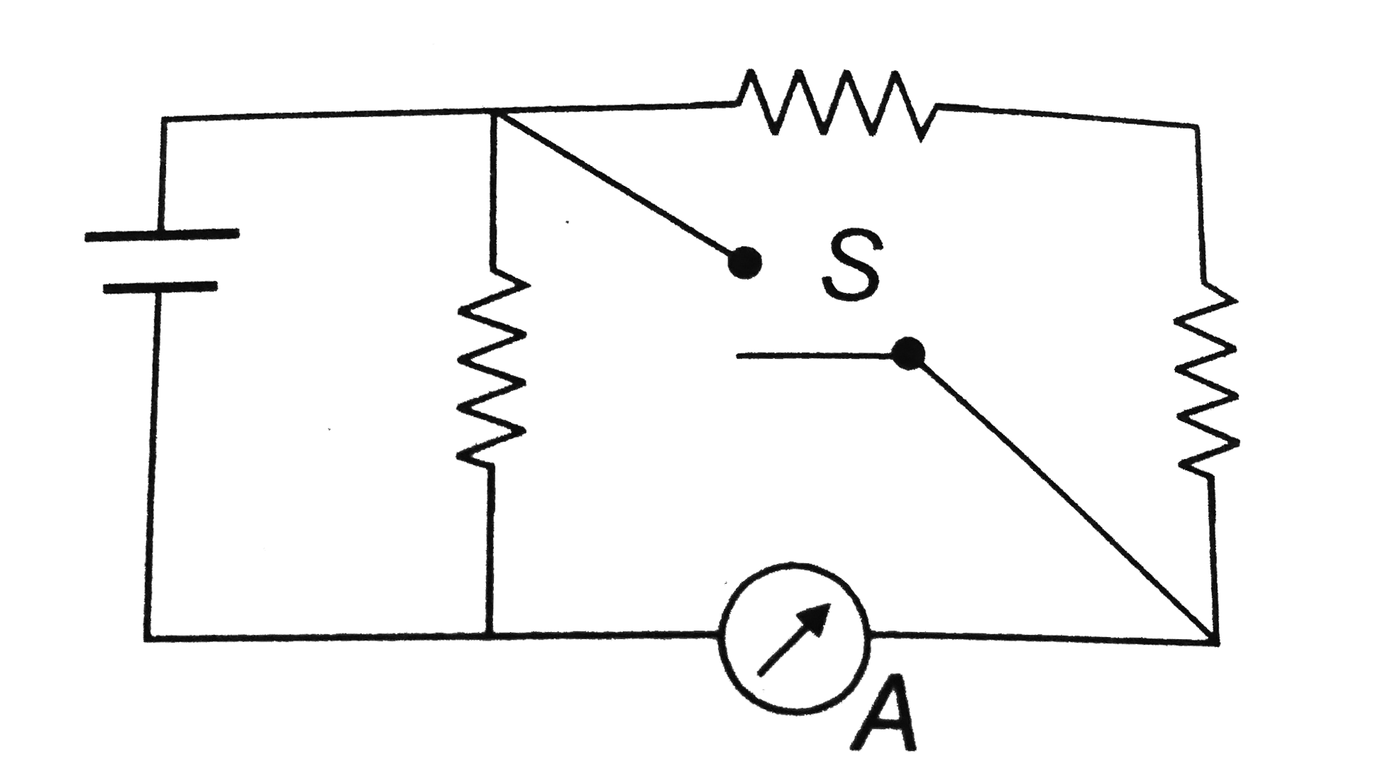
View SolutionIn the circuit shown, the reading of the Ammter is doulbed after the switch is closed. Each resistor has a resistance =1Ω and the ideal cell has an e.m.f. =10V. Then the ammeter has a resistance equal to
View Solution
