In the circuit shown, the battery, the ammeter and the voltmeter are ideal. Pick the correct choice(s) :
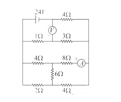
Power supplied by battery is 72 W
Rate of heat dissipation in 3Ω resistance is 12 W
The ammeter reads 43A
The voltmeter reads 22 V
The lower network of 4-8-6-2-4 is a wheat stone bridge in balanced condition since So, we remove . Now, net resistance in series with battery is 6Ω
⇒ Current through battery=4V
So, current in the three branches, starting from the top are 2A,23A,43A
⇒ Ammeter reads 23A, Voltmeter reading =24-(L) (2)
⇒ Power supplied =24×4=96W⇒ Dissipation in 3Ω=22×3=12W
Topper's Solved these Questions
- DC CIRCUITBook:VMC MODULES ENGLISHChapter:DC CIRCUITExercise:LEVEL-1 JEE MAIN ARCHIVE
Explore 93 Videos
- DC CIRCUITBook:VMC MODULES ENGLISHChapter:DC CIRCUITExercise:JEE ADVANCED ARCHIVE
Explore 68 Videos
- DC CIRCUITBook:VMC MODULES ENGLISHChapter:DC CIRCUITExercise:LEVEL-2 DAILY TUTORIAL SHEET-4
Explore 10 Videos
- CURRENT ELECTRICITYBook:VMC MODULES ENGLISHChapter:CURRENT ELECTRICITYExercise:IN-CHAPTER EXERCISE-F
Explore 10 Videos
- DYNAMICS OF A PARTICLEBook:VMC MODULES ENGLISHChapter:DYNAMICS OF A PARTICLEExercise:JEE Advance (Archive) Level - II (SINGLE OPTION CORRECT TYPE )
Explore 31 Videos
Similar Questions
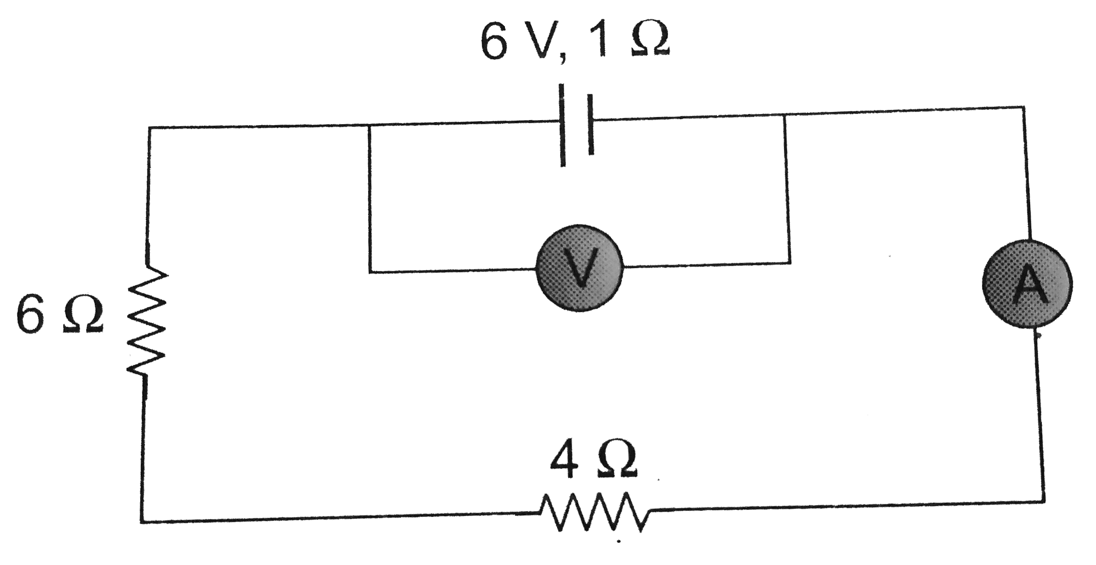
In the circuit shown here, the readings of the ammeter and voltmeter are
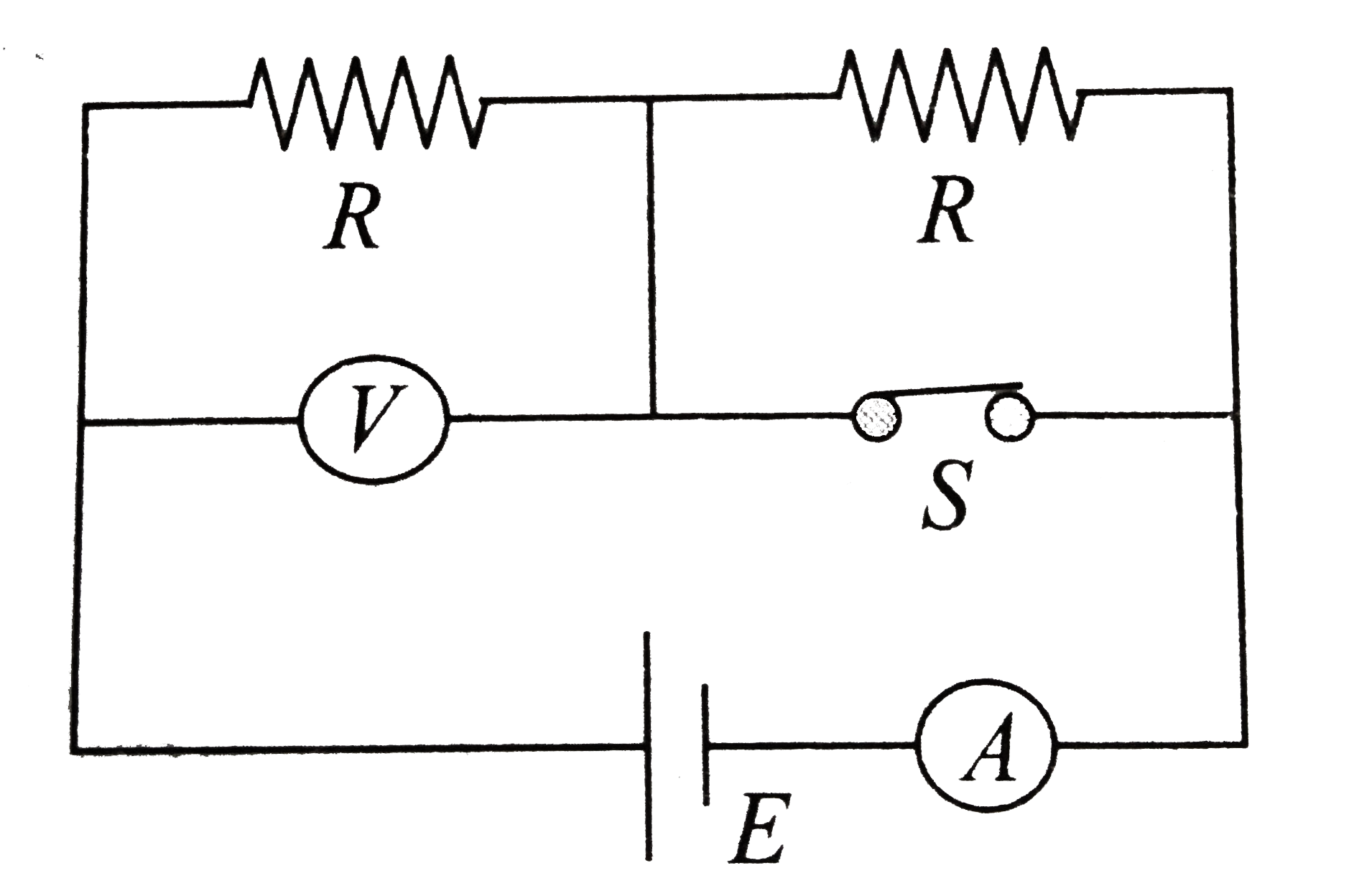
View SolutionIn the circuit shown, battery, ammeter , and voltmeter are ideal and the switch S is initially closed as shown. When switch S is opened
View SolutionIn the circuit shown in figure , if ammeter and voltmeter are ideal , then the power consumed in 9Ω resistor will be .

View SolutionIn the circuit shown in the figure, the voltmeter reading is
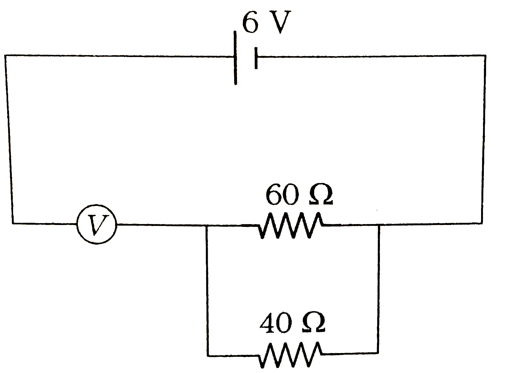
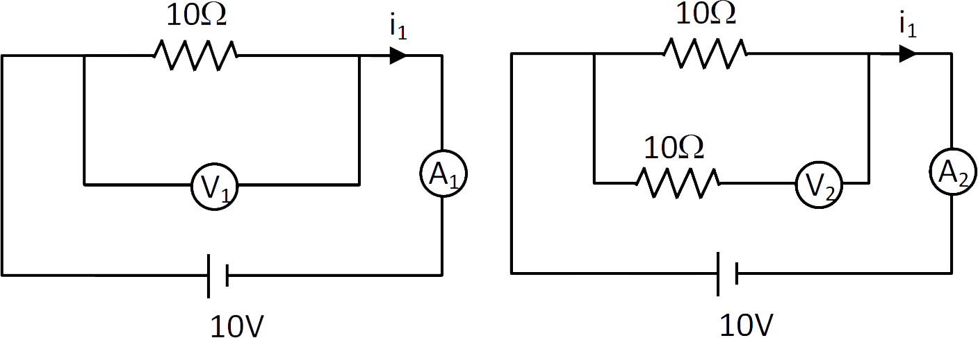
View SolutionIn the circuits shown below, the readings of the voltmeters and the ammeters will be:
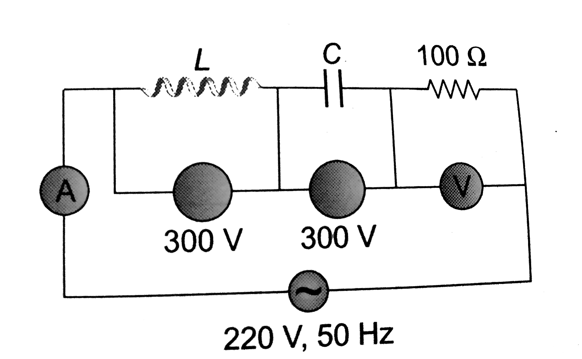
View SolutionIn the circuit shown below, what will be the reading of the voltmeter and ammeter?
View SolutionIn the circuit shown alongside, the ammeter and the voltmeter redings are 3A and 6V, respectively. Then, the value of the resistance R is

View SolutionIn the circuit shown, A and V are ideal ammeter and voltmeter respectively. Reading of the voltmeter will be

View Solution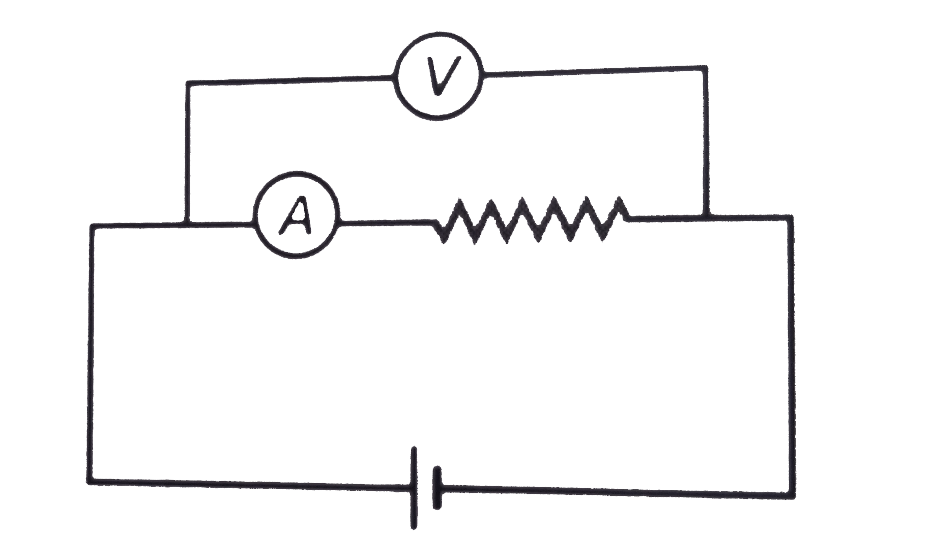
Assertion : In the circuit shown in figure ammeter and voltmeter are non-ideal when positions of ammeter and voltmeter are changed, reading of ammeter will increase while of voltmeter will decrease.
Reason : Resistance of an ideal ammeter is zero while that of an ideal voltmeter is infinite.
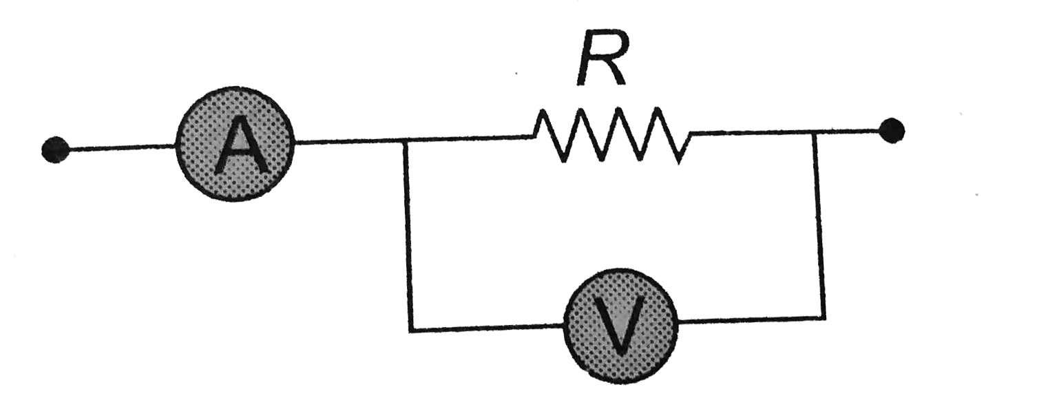
View SolutionIn the circuit shown the reading of ammeter and voltmeter are 4A and 20V respectively. The meters are non ideal, then R ia
View Solution

